3D milling - Fusion 360

Hi Guys

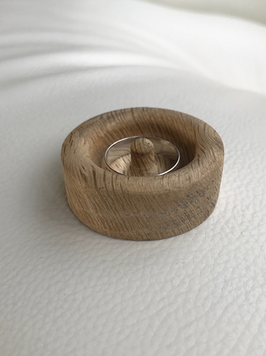
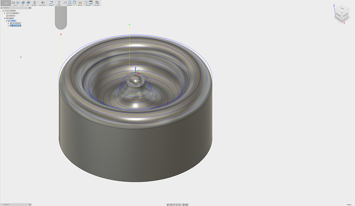
I’m keen to mill this part from wood using a 1/8 round nose cutter.

But I have little experience making 3D objects in fusion. I think I’d want to do a 2 pass program - rough it out then run a final pass. Can anyone recommend which programs to use? I’m thinking adaptive clearing then radial but machining time on the radial is like 30 minuets which seems excessive for a 40mm disc…

3 Likes

Presuming the side not in view is flat, this is a single setup job, and I would do it with two tools.

In Fusion, the easiest (IMHO) way to set it up – not the most efficient, but the easiest – would be to run 3D adaptive over the whole thing using a square nose bit to rough, leaving about 0.25mm (radial and axial) for the finishing. Then, I would use the ball end to do finish passes using contour and spiral (spiral is for regions less than about 45 degrees from parallel to the x-y plane, and contour is for those more vertical than that… It has to do with whether the horizontal step or vertical step is dominant) Use spiral for slope from 0 to 45 degrees (slope selection is in the second tab), followed by contour from 40 to 90 degrees. The stepover (spiral) and stepdown (contour) should be selected for the cusp residue you are happy with. You want to let the tool go outside the boundary of machining to get all of the way to the bottom of steep vertical walls at the outside of the part.

The time depends on the radial and axial engagement of the tool, as well as the travel speed. You are removing a lot of material with a small tool. It will take time. Check the settings and match them to the material, but 30 or more minutes is reasonable. If you prep the material as a disk rather than a square profile, that will save a lot of machine time, but the additional prep time will likely be greater than machining time saved, unless you are running a lot of parts.

2 Likes

Thanks for this, very interesting. 2 questions.

Is I use a square nose/flat mill and leaving 0.25 - and assuming it’s programmed for a flat mill will it leave enough of a radius, i.e. leave enough for a round radius to take off whats needed - this is what I’d assume would happen. On other jobs I’ve done similar but they were even simpler than this.

Second question which I also think I know the answer too, I assume with bit change you’d re-home the machine using a edge finder etc?

Thanks

UNLESS you change some of the defaults in a strange way, or do something careless in setting up the operation, none of the machining strategies in Fusion will remove material that shouldn’t be removed. When you simulate, you should see the result (turn off the toolholder, unless you model it for your setup), but leave tool visibility on, and turn on stock visibility.

Look for the red tags for collisions, and PAY ATTENTION to them. If you specify the tool wrong, you will get them. If your tool shank will touch the stock, you will get them-- this is not always a problem, but usually should be avoided-- and so on. Fusion does a good job. Once in a while, you will see a gash where it shouldn’t be,and you know you need to revisit the operation.

The second operation with the ball end will remove the stair stepping and leave small cusps. You will trade machining time for cusp size. It is easy to figure the cusp size (height over nominal) for a flat surface-- see below-- but for convex or concave it is significantly more involved. On the concave, the cusps are smaller than on a flat surface, on a convex, they are larger (concave and convex refer to the curvature of the surface perpendicular to the tool motion). Not a big issue for curvatures that are small relative to the tool diameter.

Using 0.25mm leave and 0.25mm fine axial with the first operation will leave 0.25 to 0.7mm for the finish pass (8 - 20% of tool diameter), so the finish should be pretty consistent. This is why I suggest spiral and contour rather then radial, as the radial strategy will go across the steps from roughing, so the tool load will vary.

As to rehoming: You should only need to address the Z axis. I don’t use any machines without tool length probing, but I will guess you would need to either match the tool extension exactly or rezero the Z axis.

Cusp size (on the flat):

RobG addresses this at How To Choose a Stepover for 3D Profiling - CNCCookbook: Be A Better CNC'er

I can give detail on the math if you want, but it isn’t trivial (requires trigonometry) for machining on the flat, and is more involved for curved surfaces.

3 Likes

Just an additional note for setting Z0 for the new tool. You probably can’t use your job origin to set Z0 for the new tool because you may have milled that area during the roughing stage. You need to pick a spot that has the same stock height as your origin, and that’s probably going to be outside of the area you’ve already milled. Touch off Z there and set the Z height only to 0, leaving X and Y untouched. No matter where the spindle is, when you start the job, it will travel to x0 y0 and start cutting from there. Technically, you could shut the S03 down for several days and it would still remember where X0 and Y0 are for the last job you ran. This feature makes cutting repeated parts a dream, especially if you don’t do tool changes.

2 Likes

Thats what I was wondering - how would the stock be left and stair stepping is pretty much what I’d have expected - I hadn’t considered a term for it.

I’m pretty familiar with making 2d and some 2.5d stuff, but most of my work is aluminium or wood and has been limited to brackets or functional parts. I’m just getting interested in all the 3d stuff now and making more ornate objects.

Thanks for tips on setting 0 - Unfortunately I’m very familiar with this due to many f**kups and waiting for Carbides probing tool, whilst I have made my own homing plate and written the macro I don’t use It often as I don’t like it due to the issues with loading the file. I want the easy solution…

Thanks for this guys. I had a play today and did my first job with 3 tool changes I think.

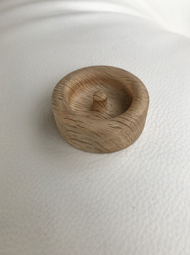
I did my first pass with a 1/8 flat, and got those lovely steps I wanted. The onto a 1/8 ball which smoothed it out. Then back to the 1/8 flat to cut out the rest of the shape. Each time I probed between changes, even had to reset the machine at one point.

A very light sand and jobs done.

6 Likes

Very nice. Ring holder, I presume? I like the way the grain reflects on the interior of the ring.

As to resetting the machine: If I have any concerns about the length of the job, or if I have a system crash during the job, I go back and regenerate the operations that are not complete, without those that are done, so as to avoid cutting air. This pretty much means I have the CAD system used for toolpath generation (usually Inventor for me, but sometimes Fusion or solidworks) open while the job runs so I don’t need to waste time/effort doing it. I hope you figured that if, if applicable, rather than taking the time to cut air the machine already installed into the stock.

Yep, I wanted a project to test tool changes and probing on that wound’t take too long. I got married 2 weeks ago and keep loosing the ring - not it has a safest place. It’s white tiger oak, which I believe is quite rare.

I have had many a system crash in my time, originally it was tough to get the homing back to the correct place - I had normal limit switches, but have swapped to magnetic. So now I can get back to X/Y usually with good precision. Today my machine decided to restart during the program (good old windows) so I just changed the top of the job height in fusion to 5mm lower and it pretty much started where I left off.

Lucky system crashes I’m good at, but I have never been one for probing in my time - I’m now changing that and using Z as a minimum requirement so I’m more accurate. Better that than by eye…

2 Likes

On a machine without tool length detection, I would probably make up a probe myself. I can’t be bothered to rerun a job, or, for that matter, futz around with zeroes for a tool change or machine restart. Life is too short.

I think I might be missing a trick. I had to probe between jobs using my home made probe and reset the Zero three times. What software are you using?

Carbide Motion for sending, since it does the job. Zeroes are retained through resets, &c, relative to home position.

You are probably not missing a trick, but…

If you have homing switches, that takes care of X and Y. The part didn’t move, so X and Y will be still zeroed. If you don’t have homing switches, you really, really need to have them (X, Y, and Z)

For the Z, the best (best is defined as easiest in use, IMHO) way is tool length compensation. That leaves your Z zero alone, but requires a tool length probe. I use a Nomad at home, and it has one. Then, the Z zero stays the same and the controller handles the difference between the tool extensions.

If you don’t have tool length probe, and don’t want to make one-- repeatability is key to avoid stacking errors in Z position-- then setting up a stop, or set of stops, to set tool extension repeatably avoids the need to rezero on tool changes. After all, the part hasn’t moved, the zero position is the same, the only potential change is tool length. Pick an appropriate extension for the tools being used on job and make them all the same.

If you use stop collars on the tool shanks, you can set up your tools to make this easy-- insert until the collar touches the collet face and you are done. I don’t like them in general, as they reduce the useful length of the tool and can slip, but they are certainly easy. Initial setting can be tricky. I have done it using a vee block and spacers. Set the vee block on end on a smooth plate, put spacers in the vee to leave the desired length of the tool below the stop, set the tool in the vee, and slide the stop down to touch the top of the block. For te spacers, I have used pretty much anything that is repeatable and convenient, including gauge blocks (overkill),adjustable parallels, 1-2-3 blocks, shim stock, whatever. With care, you can get repeatability of maybe 0.1mm or better using collars. Error sources are collar placement and variation on tool insertion-- the shallow taper of the collet causes variation in shank diameter to change the tool length about 6 or 7 times as much.

As a side note, tool length compensation and repeatable homing/absolute positioning are why I went with the Nomad. I will NEVER again work with a machine (manual or CNC) where I need to do these manually if I can avoid it. Worst was a large (manual) mill with a non-absolute DRO. We lost power in that shop a lot, since we were at the end of the (under capacity) line. Every time, had to repickup zero, sometimes hourly during the summer. I’m too old to deal with that anymore.

1 Like

Ah now that is interesting. I have a shapeoko 3 so don’t have the tool length probe - that doesn’t mean I would not make one - I just don’t know how to use one. Do you have to add a command into the G code to use it?

I haven’t looked at the details of how C3D implemented it in the Nomad. There is support in GRBL, but, from the GRBL docs (without reading deeply) I don’t know if the compensation needs to be done at the sender end or if it can be done in the controller with current GRBL. I suspect that it is still handled by the sender, since the code is a dead tight fit in the latest GRBL versions.

CM supports it for the Nomad, but I don’t know about for the Shapoko.

See, for example: https://github.com/grbl/grbl/issues/464 and https://github.com/grbl/grbl/issues/91 for basic info re: GRBL

and https://www.shapeoko.com/wiki/index.php/Touch_Plate for a sample with Shapoko (manual compensation)

1 Like

Thanks, I will have more of a read. I think its one of those features there but not turned on for a S3 so probably can’t use it.

Im currently using my own with manual compensation - likely this will be the route forwards

I had another thought, and this comes back to the mutihead change and adaptive clearing.

lets say I’m working on a bowl - I want to clear most of the wood away with a 1/4 bit. I then want to step down to a 1/8 bit to get up the curves then finish with a 1/8 round mill.

I understand I will want to leave 0.3 mm or similar on the final pass, but how to I run the adaptive clearing on the 1/8 bit without repeating the whole adaptive clearing section the 1/4 has already done?

Adaptive clearing with square end mill then parallel finishing with ball mill seems to work best for me!

1 Like

but would you jump down from a 1/4 flat to a 1/8 ball - assuming the detail was required. I don’t know if the middle 1/8 flat would be required in the middle…?

This is where things get interesting. There are a number of approaches, and they overlap a lot, so the techniques you use depends on the job and your preference and which options are available in a given strategy. Adaptive clearing doesn’t have as many options as many other strategies since it is intended to remove material efficiently, and, though it can be used for finishing, it is primarily to get the volume of material out. Don’t think of it as a surface operation like a roller, think of it as a removal operation like an excavator.

Use adaptive to get near the finish surface, then select a surface finish strategy that will do a single pass where you want it to.

As to some approaches:

Easiest is when you can get away with rest machining. For this application, that is probably not sufficient, since the tool geometry is different, but I have never tried. Might be a go if the 1/4" is ball end and the 1/8 is as well.

Next up the list is to use the angle settings. Lets say the bottom is flat. Set your strategy to clear from an angle of 0.01degree to 90 degrees. This will avoid the flat area, but the difference is so small it is lost in the precision of the machine. Finishing strategies like contour have this.

Next is use the touch/avoid options. If the area you do not want to go over again is a separate surface (there is an edge all around it) you can specify that it is to be avoided. You can also select surfaces to to touch. You may need to experiment, as these tools have a lot of gotchas. You also need to address tool containment (on center, inside boundary, outside boundary)

You can use the levels to control the tool as well. Using your top and bottom options is very helpful. For example, if I don’t want to touch the top of the part, I might set my top height to be model top -0.001mm. This will bring the operation to the top within the machine precision, but not touch it. Bottom can be used the same way. You can select features (edges and points) to set the heights as well.

Most involved is to structure the model for the operation you want. Most things I machine are machined from assemblys, not parts, so I can include fixturing (it really sucks when the tool path goes right through your new vise) and modify the model for the machining job without changing the base model. Don’t be afraid to put in features solely to direct the machining, such as a curve on the bottom of the bowl that is there solely for bounding the tool path. Don’t be afraid to cut the model up into several pieces, each of which is for a portion of the machining. Add and suppress features as needed. Use work planes and work surfaces, then hide them (turn visibility off) when they have done their job.

I hope this gives you some ideas. Note that there are a lot of good resources on the autodesk website. There was a series of webinars last year you might want to look at. Start with HSM Kickstarter (HSM is the engine. Started as independent company developing for Solidworks, Autodesk bought them, and now is core for Inventor and Fusion) at https://www.youtube.com/watch?v=aVLNGvC3GKY There is also a series for Fusion360, but I haven’t look at it since Fusion is substantially the same as Inventor in this regard. I really recommend the long form videos over the help pages or short single feature demos. The long form show the tools and options in relation to an actual job, rather than in isolation.

RE: going from 1/4 flat to 1/8 ball… It depends. If there are flat ares the 1/4 can’t get to, go to the 1/8 and use rest machining. If all of the flat is covered, go to the ball end and avoid the flat. Also, if you can get away with a 1/4 ball end-- no regions with too great of curvature-- it will be faster and give a better finish (smaller cusps) than the 1/8 ball end.

2 Likes

Yeh I would probably do this, or if the detail is intricate, then rough with an 1/8 flat and finish with an 1/8 ball.

perhaps scalloping would be a good option for finishing actually! (finer stepover than shown in the picture though!!)

1 Like