Aftermarket Digitizer

Hi Tito…

That’s a great link thanks … it shifted my thinking about it as an application …I will definitely take a much closer look at this now…and will let you know what I find out…

As always much appreciated…

Regards,

Ed

Hi Matt,

I did check this out … It requires a conductive surface …Might work if I can find a way to metalize the surface of the sculpting polymer that I work with …

Worth poking at…

Thanks

The Estlcam contour mapping is intended to let you project an existing CAM project onto the “probed” contoured surface, and as I understand it you’re wanting to probe a handmade carving, and then replicate at scale and volume.

I don’t know of a way to export the contour results using this Estlcam feature into a usable map, model or file, but the notion of this operation intrigues me. There might be a way to save the contour results, but I’m not certain as I have yet to use this in any project (yet).

Hi Rob,

Ok I think I get it now… a bit of an unwieldy application, labor intensive to support with narrow market… and I understand where the limitation is …Thanks you saved me some time and effort by clarifying … I will go learn Z brush or Rhino or something or resort to some form of digital scanning.

As I told Meg I plan to buy your Shapeoko XXL unit in June or July by then the your zero probe will be launched …

Regards,

Ed

Hi Jim,

Correct with respect to my intent … with respect to your second point …I thought it was a bit of a stretch as well but an interesting one providing the file can be manipulated and the conductivity issue resolved… however may not be justifiable given my somewhat narrow application.

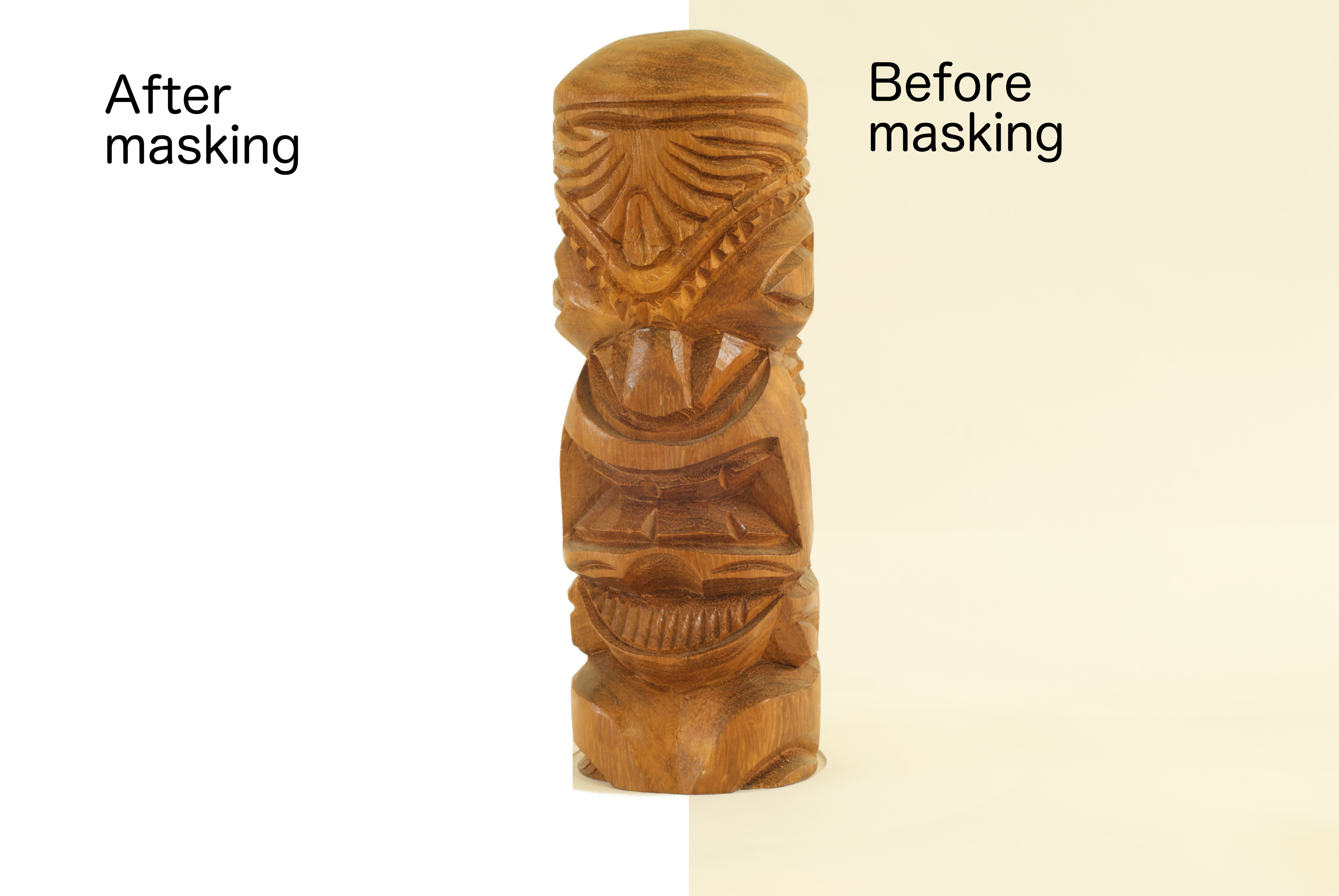
So I was curious and got a copy of PhotoScan. I shot a little tiki statue that I have–being carved and wooden, it seemed like the kind of thing @edzacly1 might be working on. I used just ordinary indirect daylight for lighting, at f16 and 1.5 second exposures (obviously with a tripod and remote shutter release). I was using a Nikon D200 with a 50 mm f1.4 lens. I then set my tiki on a Shimpo ceramics turntable under a sheet of white paper with a hole in it for the tiki, and another piece of white paper in the background. Like so:

And so:

I had the camera autofocus, then turned the focus to manual so the focus would be consistent in all photos. I took 38 photos (tiff format) rotating the turntable a little bit at a time.

I then used Gimp (an open source cousin of Photoshop) to mask the photos, removing (almost) all but the tiki and saved the results as tiffs again:

I then imported them into PhotoScan and after playing around with the settings ultimately ended up with an stl file and an obj file. The results I wanted took less than 2 hours of processing in Photoscan on my bottom of the line mac mini–add that to the hour it took me to do the masking. The model that Photoscan made from the photos (and the point cloud derived therefrom) was 2.5 mm tall when I imported it into MeshCam. Unfortunately, MeshCam was able to scale it only about 3x. So I took the stl into Evolve (what I use for my 3D modeling of parts to be milled) and scaled it 64x so that it was about 6-7 inches tall (a little smaller than life size, which is a bit over 8 inches). While I was in Evolve, I had some fun. I think maybe Dr. Jones would approve:

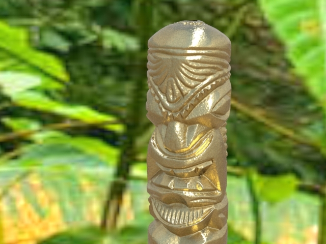
Or maybe more dramatic:
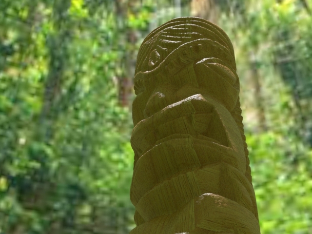
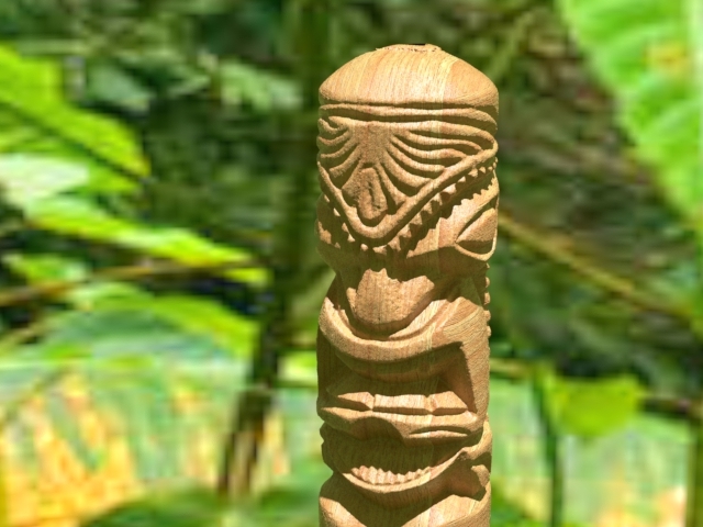
Or just plain wood:

Finally, I tried importing again into MeshCam. I added tabs at the top and bottom, and used the following settings to generate gcode (using 1/8" square and 1/16" ball nose mills):

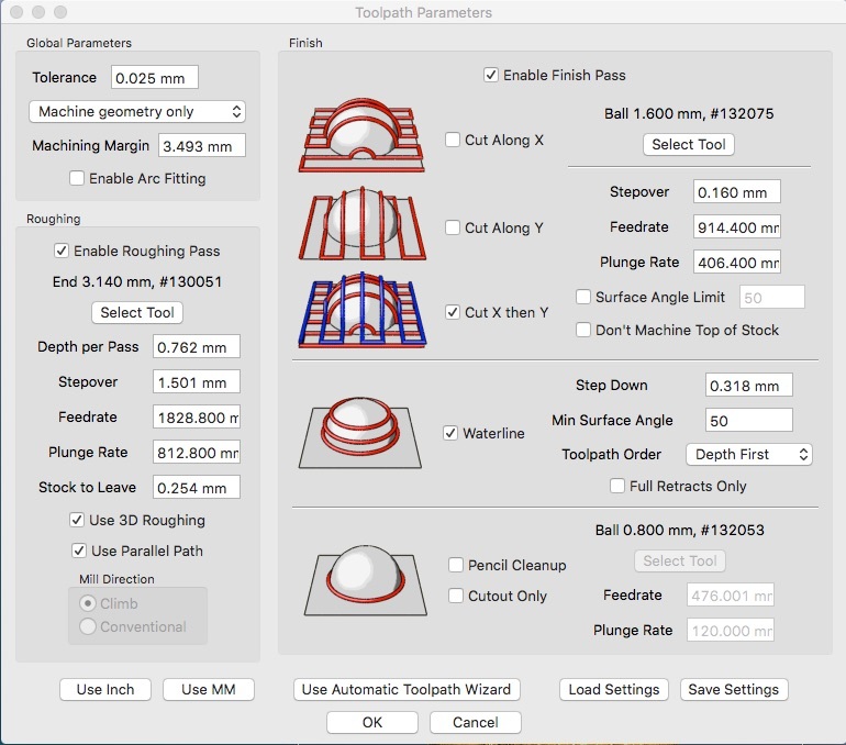
The predicted cutting time is something like 333 minutes. Here’s the simulated first side (I generated only one side):

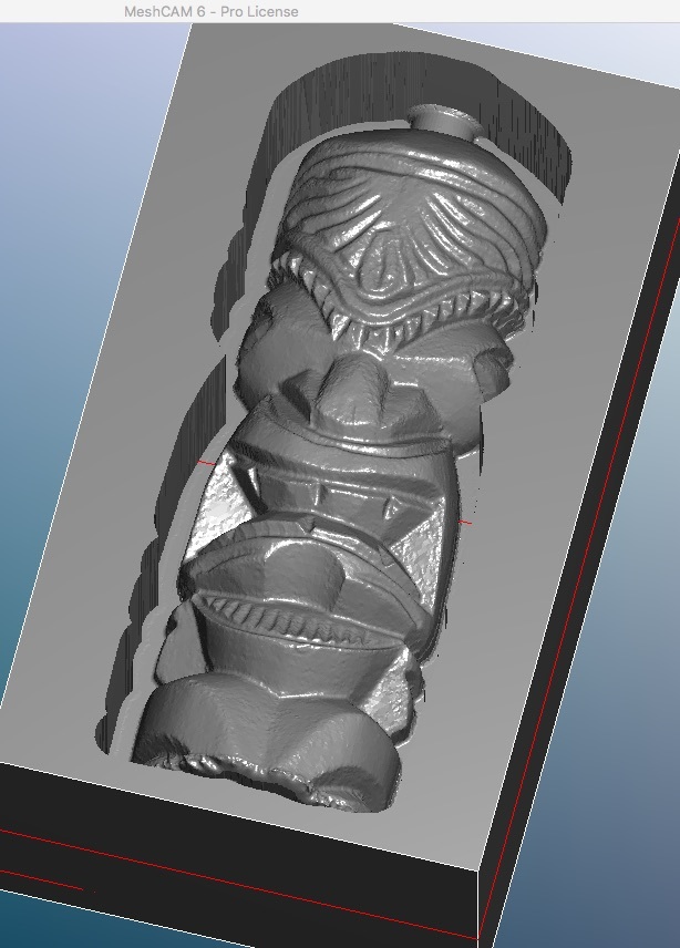
This is for a blank that’s 101.6 x 177.8 x 60.0 mm (4" x 7" x 2.something"). I haven’t run this on my Nomad yet, but might try in a few weeks when I have a little more time. If anybody wants to have a go, here’s the gcode.

Rough:
tiki pine (4500 rpm) 1 rough.nc (1.0 MB)

Waterline:
tiki pine (4500 rpm) 2 waterline.nc (1.4 MB)

Parallel:
tiki pine (4500 rpm) 3 parallel.nc.zip (2.6 MB)

Note that the last one is zipped. Unfortunately, the original stl from Photoscan was 25 MB, and after scaling in Evolve it was 110 MB. So obviously I can’t post them here.

The proof, of course, is in the milling, which I haven’t done yet. But this seems like a pretty useful way of acquiring models for milling.

1 Like

Last time I looked at photoscan, the only option was the “pro” edition at a price so high it was totally out of reach. Now that there is a “standard” version, it’s within the realm of reason for the right project. Had totally forgotten this existed, so thanks for the reminder!

And if you have an academic affiliation (student, faculty, probably anything with an email address ending in edu), you can get it for $59. : - )

Hi Tito.

Go for it …Drama is good

Well I can see that you are driven by innate curiosity … I had to read this over a few times in order to visualize the process … Thank you for taking the time to demonstrate and document …honestly… I have to say given your excellent results that I had clearly underestimated it’s potential… that file looks ready to go…

From what I gather - Essentially the Shimpo ceramics turntable was sufficiently stable during each sequence of the 38 photos… once the 38 photos were loaded, the Agisoft PhotoScan is able to sequence / combine those 38 digital photos so as to create a composite 3D model as stl / obj file…. additionally the Agisoft PhotoScan is able to create a point cloud, with a processing time of 2 hrs or so … from there you Exported the stl file to Evolve in order to scale it up x 64 so as to retain the original dimensions / scale, from there to mesh cam for the gcode…

On review I would have to say: Impressive and very accessible…

On that note…due to your persistence and to your credit …I am in the middle of researching this process (see below) which might be applicable to Bas Relief (all my art will be Bas relief as opposed to 3D) - the process is noteworthy because:

  1. Has Support for Arduino UNO / grbl Controllers.
  2. Works with photos … as such it has the potential to cut down my development cycle dramatically as it could allow me to create pieces from stock or acquired images that I could then manulipate / stylize… :

https://www.picengrave.com/index.htm

CNC photo engraving solutions for spindle & laser diodes.
PicEngrave Pro 5 + Laser was developed for the
Hobbyist and Professional engravers and now has Support for Arduino UNO / grbl Controllers as well.

Their software will generate gcode for 3D laser engraving, or 3D spindle relief for grbl or Mach3, but it requires a depth map image…

Depth Map Image

https://en.wikipedia.org/wiki/Depth_map

In 3D computer graphics a depth map is an image or image channel that contains information relating to the distance of the surfaces of scene objects from a viewpoint. The term is related to and may be analogous to depth buffer, Z-buffer, Z-buffering and Z-depth.[1] The “Z” in these latter terms relates to a convention that the central axis of view of a camera is in the direction of the camera’s Z axis, and not to the absolute Z axis of a scene

Examples
https://www.google.ca/search?q=depth+map+image&rlz=1C1CHFX_enUS594US594&source=lnms&tbm=isch&sa=X&ved=0ahUKEwiIuNH_2LrTAhWK64MKHev9AnUQ_AUICCgB&biw=1920&bih=950&gws_rd=cr&ei=xLD8WNHCA-OGjwSui4bwBg#spf=1

Your Thoughts?

Again thank you for demonstrating and showing the how to…

Regards, Ed Zac

@edzacly1, your summary is essentially correct, except that after taking the photos and before putting them into Photoscan, I had to modify them to replace everything that wasn’t the tiki with white. (Btw, the Photoscan docs say not to do any other manipulation–color correction, compression, scaling, etc.–before importing them into Photoscan.) I think there are tools in Photoscan for doing this modification, but I didn’t want to take the time to figure out their tools, so I used Gimp for that.

Oh, and the Shimpo was perfectly stable, but I think that’s really not that important (if at all), since based on other photos, Photoscan will try to figure where the camera had to be to take the picture. I mean, some people apparently take pictures of environments (e.g., the village square) with their cell phones and get at least some results from Photoscan. So my Shimpo comment was almost an irrelevant detail I guess.

As far as the Arduino connection, I realized my D200 doesn’t have an IR sensor, so the plans outlined in the link a few messages back wouldn’t apply in my case. If you go that route, make sure your camera has a way for the Arduino to trigger it.

As far as depth maps go, I believe Photoscan can produce them… Found it–yes indeed:

Anyway, I’m only about six hours ahead of you in terms of Photoscan experience (got a lot of hours of Photoshop, Maya, and Evolve though which probably help), so take everything I’ve written with that pound of salt.

Edit: The depth maps are as seen through a particular camera as placed by Photoscan based on one of your photos. I don’t know if it can produce arbitrary depth maps (like perfectly orthogonal ones) de novo. But many 3D modeling and rendering packages certainly can if it comes to that.

1 Like

Well I have to say for 6 hours ahead …You learn fast …

I use Corel Draw a lot for photo editing, removing backgrounds etc… I didn’t see the white issue as being pivotal in the process given that your initial result was off white… I gathered that you wanted a pristine series of elements which is a good precaution… thorough …

Now I would assume that the more photos the better the resulting file… I’m wondering if was there a minimum number of images necessary to support a full 360 view? I will have to read up…

I have a few questions given your depth of knowledge…

  1. What do you think would be a minimum resolution for a picture to be in order for the depth map to work properly in Photoscan?
  2. As a single file / image - I am assuming that the Depth Map from a single image would have varying depth which would be dictated by the placement of the camera relative to the object… For instance: Let’s say we downloaded (off the internet) the image of your scary Tiki friend below (as a single image) and then processed it via Photoscan, again as one image …… now when you machine it on a CNC router (as a bas relief) would it be thicker at the bottom than at the top due to the perspective of the shot, I am thinking that once machined as a bas relief it might be a ½ thick at the bottom and a ¼ thick at the top…( depending on how you scaled it)…. Or is it of a consistent thickness ? not sure how that works …

While I am still looking at the digital scanning via a probe as a backup I am ( With many thanks to you) looking at this more and more as I can readily see that it could really shorten the development cycle…

Regards,

Ed Zac

Sorry if my explanation was confusing but I have to clarify: depth maps are produced from 3-dimensional data and not from simply a single photo. What I Meant to say is that a single photo in Photoscan is used to pick the perspective from which the depth map will be generated from the 3D model that you generated earlier in Photoscan from a set of photos taken around that object. Hope that’s more clear.

As for the minimum resolution of you source photos, the docs say (IIRC) at least 5MP, but more is better, all else being equal.

1 Like

Still not so sure…

if the example below was generated from bas relief art then your reasoning stands because the file would likely have ben generated from multiple shots…

However I think some depth maps are based strictly on the grey scale from a color or black and white picture, case in point …if the item below was generated from a flat 2D painting then the only means of creating depth map are from the grey scale… once the image is converted from color to black and white… I am speculating… anyway this is what is gnawing at me…if this is the case then possibly if you took one of the images from your Tiki sequence it might render a similar result to what is pictured below…

(below) I am not sure if it was a Bas Relief to begin with or a painting and if multiple images contributed to the Depth Map image… PicEngrave did not elaborate, however what I did find really interesting was that you could according to Pic Engrave edit a depth map…as a result I am getting more and more interested in this process particularly if you can edit the topography… it’s an amazing capability…

https://www.picengrave.com/Gallery.htm

I asked this question to PicEngrave

What is the minimum resolution required by your software for the picture as used below ?

Response:

We recommend a minimum of 96DPI resolution. The original was a Depth Map image that I edited.

Anyway I am going to get the software from PicEngrave after I get the Shapeoko… and will do more research in the meantime …

Thanks as always for your input I would not have looked at this if you had not persisted as I was operating on information that was close to 5 years old… and had no idea that it had evolved to this extent…

So what’s your take on this? did it start out as Bas relief Art or was it a painting?

Respectfully Ed Zac

1 Like

I’m no expert, but I don’t see how one can go from a painting to bas relief. Doesn’t mean it’s not being done–for all I know maybe it’s super easy and I just don’t understand.

I saw that bas relief on their web site–but all I found was a video of it being rotated a little back and forth so you could see it was a bas relief. I didn’t see any further explanation.

And of course, one can create depth maps from scratch by making illustrations in grey scale. But all this does is makes the things that are white have the highest elevation, the things that are black the lowest, and the greys are in between depending on their brightness.

That image will not work AS IS very well because it has no definition around the parts that you need to have good definition for. All the ones they print over there start with that and they manipulate it in Corel Photo Paint.

See forum here:
https://www.picengrave.com/forum/viewtopic.php?f=19&t=80

When it goes from:

To this:

Then it is ready.

I ran the second version through IntelliG-Code and it came out great I will have to post a picture soon.

Ok as promised here is the pictures.

Ok a few things MDF is not good for this, it tears like paper so it doesn’t hold definition well.
On the other hand the top picture I used the modified photo, the bottom I used the one posted. You can see the lack of detail on the second one and this is due to the lines not being darker like they are in the first one.

This was done through IntelliG-Code Picture 2 GCode generator and it generates Laser codes as well.
Hope that helps!

1 Like

Greetings Roger,

Lots of questions…

First, thank you for the input… I could not progress with out it.

In both instances It would be interesting to see what the original image looked like … I am assuming that these were paintings…?

As I use Corel… Are there any tutorials that you can think of for editing the depth map in Corel? I would like to get a feel for the nuances of editing process…

With respect to Intelli G-Code , Picture 2 GCode are both of these are standalone GCode applications or are they incorporated into Pic Engrave software …?.

Sorry I am new to the software side of this process. and I would really like to explore it as it could replace or augment some of my conventional methods for producing patterns. .to that end I could use an illustrated overview can you suggest anything ?

One more question: if you had the choice of choosing between an original 3d object or a hi res image would you prefer generate your file from an image or would you prefer to to physically digitize a 3d object ?

Again thank you…and thanks to Tito for pointing me in this direction to begin with…

Regards, Ed Zac

Ok so I don’t know how they edited the picture in Corel, I just went to the forum in PicEngrave website and I copied the photos shown in the prior post. For the bird I used the second picture I posted. This was some how manipulated in Corel based on what was stated in the forum, (The link is in the above post of mine as well if you want to read further on that).

The drawing that was posted by you was used to create the second carving. you can see that it is not as defined and the reason being is there is no DARK lines on the edges where as the one that I found in the Forum that was edited in Corel had clear dark lines defining the edges which makes for definition on a carving.

So I’m sorry I don’t know how to edit them, it was just something I thought I would bring up because I tried one in the past and then realized I could share my same issue with someone else. If you figure out how to edit it in Corel please share as I am interested also.

IntelliG-Code is a GRBL controller software that I wrote and it includes many G-Code generators built into it. It does both router and laser G-Code generation. It works similar to PicEngrave but it doesn’t have all the same features, however I have been adding more features quite often recently.

As far as digitizing objects, I have not done much of that. I have designed objects quite often in CAD software. I have also 3D printed and CNC’d many things. I have tried the ReCAP program by autodesk, it’s pretty cool but I just used the trial version.

Thanks for responding Roger

I haven’t bought the Shapeoko yet but I’m planning to purchase it in June…

If you’ve read some of my previous post then you’ll see that I’m trying to figure out whether or not I should produce artwork conventionally or if I should try to embrace this type of software to do it… I’d like to try to go to the software route because it would reduce my product development cycle… substantially… while allowing for greater experimentation.

In the meantime I plan to acquaint myself thoroughly with this process so whatever I find out I will pass on to you through this forum… if you’re interested.

I’m reasonably good with Corel so I should be able to figure some of it out. I found this link it’s very brief but does give some insights with respect to the method…

As I said I will continue to research as I need to understand the workflow associated with the process…

Hi Tito,

Update,

Ran into this… thought you might find these youtube videos interesting…


I am slowly compiling a process for Bitmap to bas-relief…

Fascinating stuff cant believe what’s out there … I am still doing a lot of research and will start to attempt creating some files this weekend … Thanks for getting me started …

Ed Zac