Try that in Carbide Create as a V-carving?
@kevCarrico, that is not unexpected behavior from MeshCAM when there are many “islands” to machine. The only thing I might suggest to try, is to first do the eagle alone by drawing a Machine Region, and then go back and draw a keepout region around the eagle and see if MC does the “perimeter” with less back-and-forth.
If the letters were recessed into a flat plane, you could use the Depth First option in the waterline finishing, and MC would try to do each recess before moving on to the next. But with the continuous “moat” around the raised letters, MC doesn’t really have a way to optimize that.
Would you consider attaching the raw SVG file (probably zipped)? I could take a look at importing it into SheetCAM (2.5D-only CAM) and see if it behaves differently around the letters.
Randy
thanks… but not interested in a vCarve!
okay, this board won’t allow me to upload an SVG or a ZIP, so i have posted the ZIP here:
thanks again for your time!!!
kev
Kev, sorry, no dice. I can load the SVG into SheetCam, but without an outer circle SheetCam’s odd/even way of defining recesses inverts the design, so the letters and etc. are the pockets. The blue areas in this screenshot are what’s machined, but the gcode throws quite a few “invalid arc” errors and there seems to be a problem with maybe a couple of the outlines (the eagle seems to be wearing a bandolier and carrying a corncob pipe or something…)

The light blue thin lines are the rapids between the pockets.
I don’t have anything that “speaks” SVG so I’m not able to edit the file.
At least in this case, MeshCAM is doing a whole lot better at working with the file… 
Randy
no worries!
thanks again, and thanks for caring, but whether the design is inverted or not is not the concern.
i am only seeking tool path efficiency!
thank you, sir!!!
LOL on the corncob pipe thing… here is what my initial cut produced after 4 hours when it “completed”:
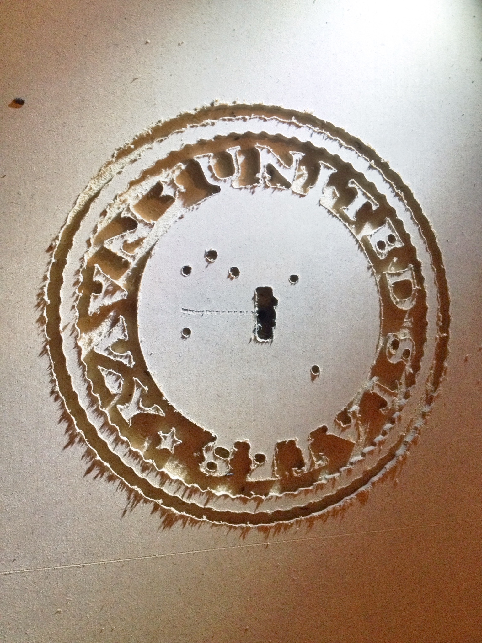
the random holes in the center crack me up!
Those ‘random’ holes are where MeshCAM determined your mill would ‘fit’ into the anchor and wing.
Try again with a smaller mill. And your source image definitely has issues that show up outside a ‘drawing’ application.
For the purposes of your tests I suggest you grab a piece of pink foam from Home Depot: Foamular by Dow Corning
You can run through this stuff pretty much as fast as you like without endangering your mills etc, which will reduce testing time significantly and save wear on your cutters. I use it routinely with a .125" end mill at about 7500rpm, 75-85 IPM, 37 plunge, 90% stepover, 100% step down, and I’m pretty sure it could go faster. Tip: give everything a quick wipe with a dryer sheet to make the styrofoam chips easier to clean up.
again, i’m not interested in a perfectly-cut result here — i am very much concerned with the lack of tool path efficiency.
i have plenty of waste stock, wax and tools from my shop; i am simply questioning meshCAM’s tool path efficiency… which, to me, went fully insane on this pattern.
Any image work I have I just use .svg / fusion 360. Crazy efficient.
-Hank
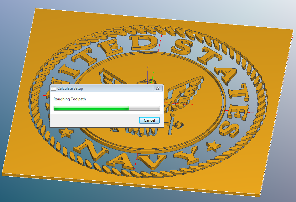
OK, Kev, I have a workable file in SheetCam. I found an online SVG-to-DXF converter, then I needed to do a little cleanup of the DXF. In the SVG there is a spurious circle just inside the outer border of the rope outline. That is actually what was causing the inverted machining areas when I imported the original SVG into SheetCam. (When I loaded the SVG itself into SheetCam I got an error message about overlapping contours too, which I didn’t get from the translated DXF.)
I had to specify a .032" endmill to get in all the detail of the eagle. Not knowing your machining parameters, I used a .090" total depth, a .016" stepdown (50% of the cutter diameter), a 50% stepover at each level, and a cutting speed of 20 in/min. I have no idea if those are anywhere near appropriate. I simulated the cut in CutViewer (from which the above is a screenshot) and got a cutting time of 4-1/2 hours for the 159,000 line gcode file.
The toolpath is actually no less crazy than the one you show above. The eagle cuts first, but then the perimiter is a big moat with many islands to outline and clear out between. If you have cutviewer I can zip and attach the nc file and you can take a look at its progress yourself. (EDIT: no, I can’t. I forgot this board won’t accept zip attachments.)
Randy
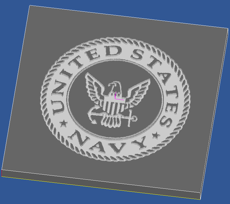
Here’s how I’d do the logo in MeshCAM. I took the CAD file of your logo and drew a box around it to represent the rawstock (box size doesn’t matter, but its presence provides the correct up-vs-down of the logo areas with the spurious circle just inside the rope border removed). I did clean up the three little spots under the eagle’s neck feathers, and the top edges of the shield stripes to give a more continuous edge.
I imported the DXF into MeshCAM and gave it a thickness of .09" (my assumed carving depth). I kept the Program Zero at the center top of the logo. I set up the cut like this:
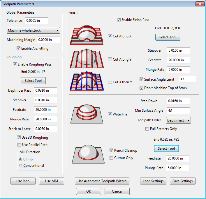
I am roughing with a .0625" end mill and unchecking Use Parallel Path. This way the roughing will tend to follow outlines rather than straight-line lawnmowing, which should make the roughing toolpath a little more efficient. I specified Machine Whole Stock with a margin of zero, so really the cuts will be restricted to the absent (recessed) areas of the logo.
It’s calculating right now, and will probably be 20 or 30 minutes given my usual .0001" calculation tolerance.
I’ll update this post or reply with a new post when I have the MC toolpaths.
Randy
Another option that I use, is to also use machining regions to specify smaller areas to constrain the cutter. Create a toolpath, then choose another area, then rerun the toolpath without changing any settings. Continue over the entire work piece.
Actually, forget what I wrote above. I can get the roughing, waterline and pencil finishing, but cannot finish the broad “absent” areas because there is nothing to machine there. So I get a roughed carving with nice edges but not the finished flat bottom. This logo can’t be machined from the SVG/DXF as input.
An STL with material under the recesses, (or a B/W bitmap processed as a bitmap) would be possible to do.
@FlatBaller, I do the machine regions too on occasion. I machined these louver simulations a row at a time to reduce the back-n-forth.

There was a lot more machining, then it looked like this

Then I bent it up to prototype what would be a punched sheet metal enclosure.
Prototype on top, production enclosure on bottom
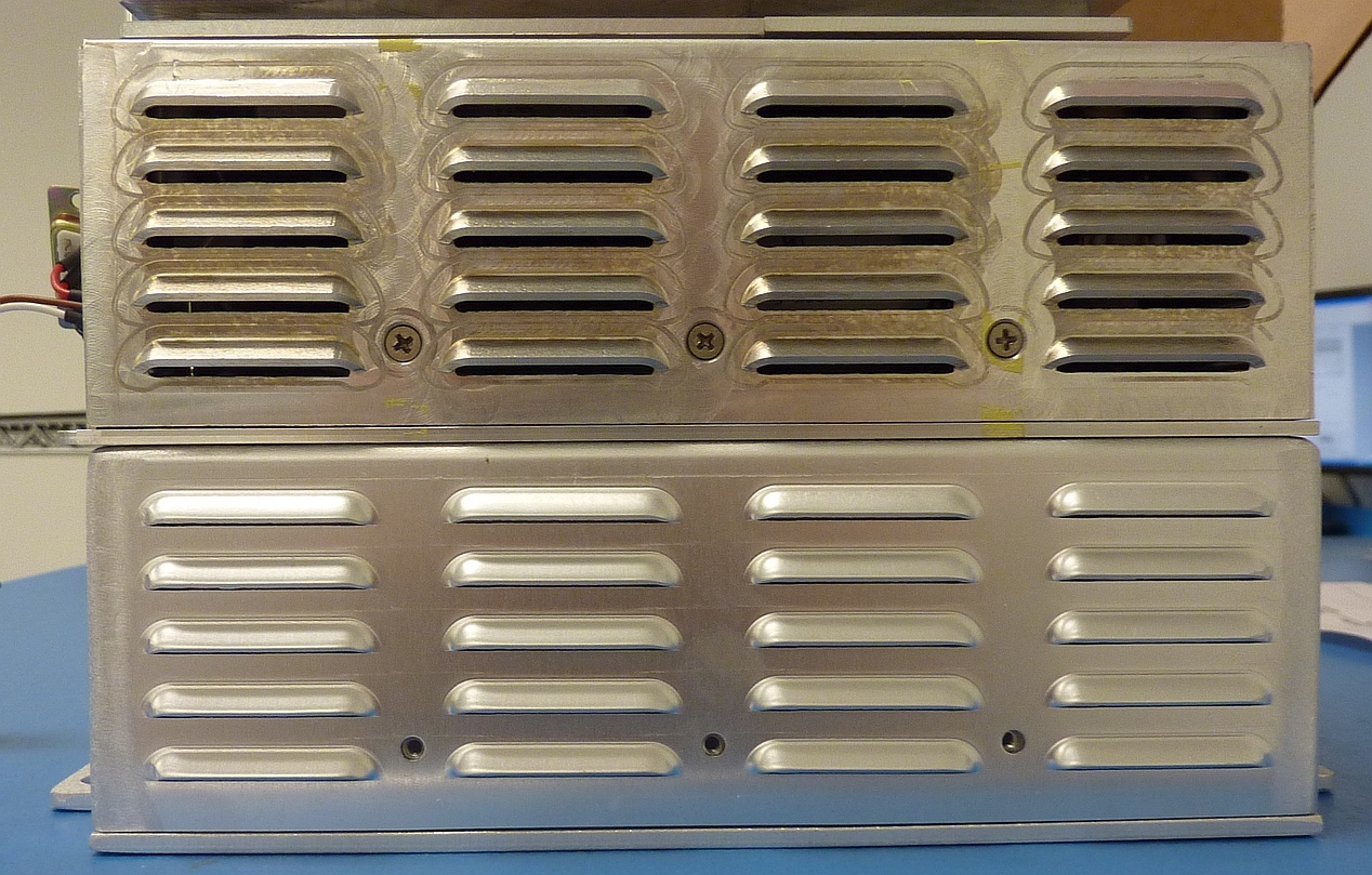
But that’s far afield. Louvers machined using MeshCAM, broad cleanout machined using SheetCAM, all on my Tormach. Simulating a .063" aluminum enclosure with .125" high punched louvers by machining a .188" thick plate…
Randy
thank you for all your time – your various responses/posts are very much helping me to understand a proper cutting approach.
again, i learn something new every time!!
thanks for the reply!
this is a vector, not an image, but i am VERY interested in fusion 360!!
1 Like
shouldn’t MeshCAM have told me that my current “toolset” was unable to machine this pattern?
i mean, as a coder, how difficult is that?
Kevin, MeshCAM will certainly machine your file. You showed a screenshot above. But with 2D input, it is a matter of cutting the outlines all the way through the material (or to the Max Depth limit)–there is no “pocketing”. See Robert’s blog where he introduced DXF machining: http://www.grzsoftware.com/blog/how-to/dxf-to-g-code/ It is for things like brackets etc. that are outlines, or outlines with holes in them.
If you can take your SVG and extrude it as a solid on top of another “base” solid, MeshCAM could machine it as an STL solid. If you convert your SVG to DXF as I did earlier in the thread, SolidWorks could do that. But SolidWork’s own limitation is that it will only accept one level of DXF outline nesting at a time, and you would likely spend a whole day just parsing and importing the DXF.
This is actually a very complicated logo. I didn’t show SheetCAM’s toolpaths above, but they were not much different in general than MeshCAM’s.
Given the resolution of most home (and frankly commercial) CNC machines, there is no shame as exporting your logo as a bitmap of good high resolution. MeshCAM 6 64-bit will allow bitmap input of up to 90000 pixels per side.You can then machine the logo utilizing MeshCAM’s grayscale-to-height to form the relief.
But, you might be happier searching for a program that works closer to your expectations.
Randy
1 Like