Can anyone point me to a 12v output on the Carbide boards?
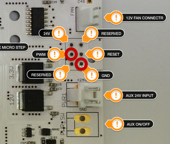
I remember the fan ran off 12v, but are there any others? I’m making the move from magnetic reed switches to proximity sensors - and they need 12 + volts. I am considering using the 24v output pin as a source.
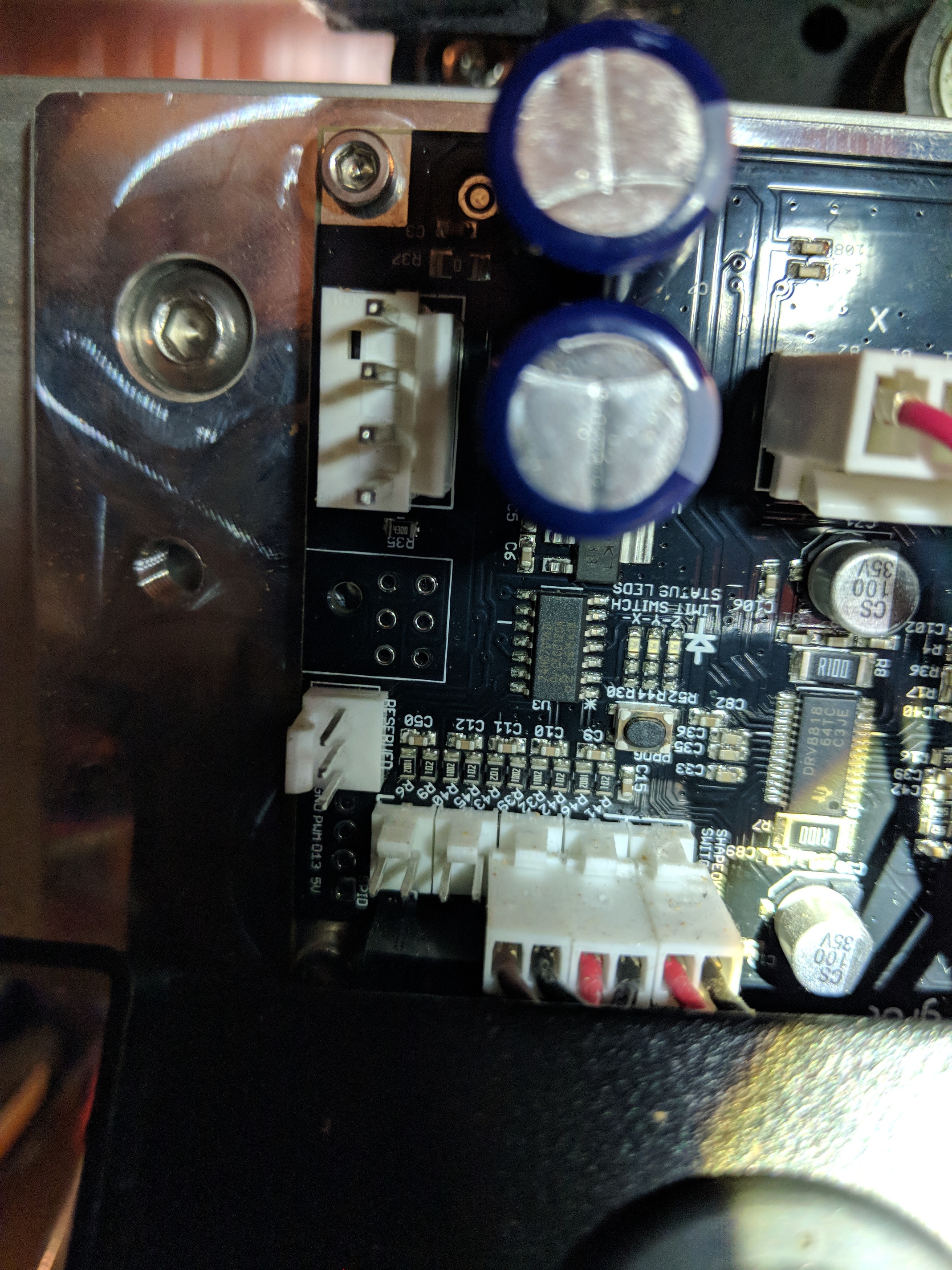
Just as an update I’ve tapped into a 24v pin - I can’t find a 12v pin as the fan connector does not exist on my board.
However I cannot seem to get the switches to work. They are NO and whilst the light turns on when close to a metal object the machine seems to think the switch is on at all times. Suggesting there might be some leakage through the switch. This leads me to believe that I need to find a 12v pin to test.
As another update, I dropped the voltage from the 24v pin to 12v, but the same issue persists. Whilst the sensors do not show as being triggered on the switch they are triggered on the board.
There’s also the option of just getting a cheap 12v DC wall power supply and running the cord alongside the other cables coming into your machine. Depending on the design of your switches, you may need to connect the ground from the second power supply to the system DC ground.
Where would you plug/solder the LED wires to on the board? I haven’t been able to find an exact answer for this since the newer boards don’t have a fan plug.
I’ve already ordered the 24v step down converter and 12v leds. However yesterday I took the cover off the board and saw that my board actually has a connector labeled “RESERVED” where the old “FAN” connector was. From my research it seems that the “RESERVED” connector is for the touch probe however I was wondering if I could instead use it to power my LEDs?