Hi, My plan is to make 80x19mm holes using the BORE operation in Fusion 360, helical cutting using a .25"/06.35mm flat end mill.
The cut starts off circular but then ends horizontally in an oval. The belt seems plenty tight on the X.
Also, let me add that I just noticed the Z goes off the lower end of the Z rails at some point down.
Should I raise my spoil boards for this too?
Any recommended posts on how to accomplish this without messing up the Tram? Thanks
Never allow a cut to be so low as to run the carriage off the rails — hopefully you haven’t damaged the V-wheels.
Yes, add a spoilboard or use a spacer or a fixture to lift the work up sufficiently that that doesn’t happen.
You may need to leave a roughing clearance and experiment w/ climb vs. conventional cutting for a finishing pass, depending on the length of the endmill.
I use daily the Carbide3D 1/4" flat endmill.
The SO3 did almost 3 holes until I was able to see past the dust shoe. I realized that ovals he been created.
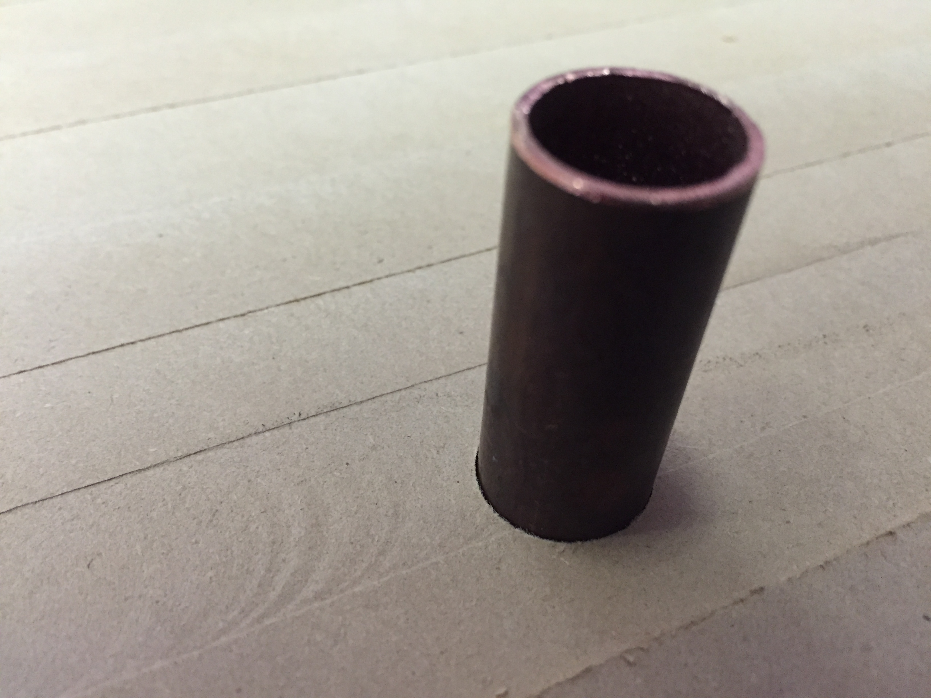
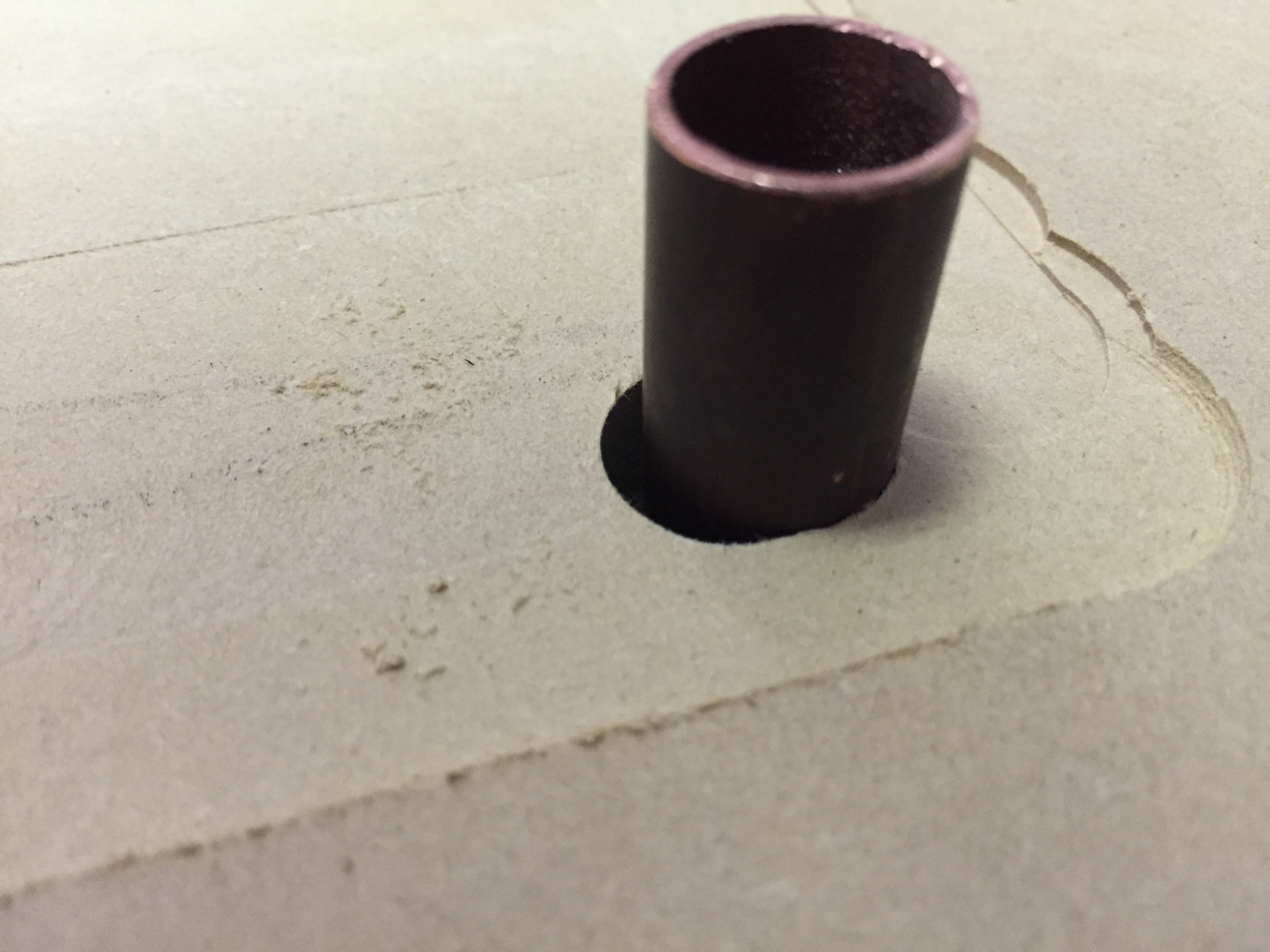
An observation, as far as I can see the copper tube doesn’t really slide at the basin of the Bored hole, it almost seems round, but I will measure that later. The entry area at the top of the hole seems to be more oval, as seen in the 2 images first posted.
Questions:
When the lower z wheels go off the vertical rail there is an opportunity for the z plate to rock side-to-side, or swing forward and backward a bit?
Has anyone extend the z rails or added limit switches to stop the z plate? Maybe, the elect onics wont allow this?
Spoilboard modification:
I guess there really isn’t an easy way to raise the spoil board to avoid the distance issue.
Thanks for your feedback!
Tem
Correct.
Extending the rails exacerbates lever effects and lessens the rigidity of the machine and creates clearance issues.
Rather than raise the wasteboard, put a second board on top of it: http://www.shapeoko.com/forum/viewtopic.php?f=37&t=8332&p=65068#p65068
Adding a spoilboard on top of the existing spoilboard would be great and it would almost work if I didn’t need to use nearly the full cut depth for a clients project. So, utilizing the spoilboard at its current height/depth is necessary.
I am planning on using a work holding system designed by Marius Hornberger (YouTube).
I have cut all the parts except for the 80 holes into the spoilboard.
I assume the router is mounted at it’s lowest point in the bracket and can’t be lowered further?
1 Like
Correct, Dan. I need to bore into the MDF about 18-19 mm. After about 8-9 mm the circle begins to become oval, at least from what I remember.
I think this is working.
I stacked the front wasteboard under the back wasteboard. Sorry, I think the image is at an angle.
1 Like
I bought a couple extra long 1/8 and 1/4 endmills for exactly this reason. I like to be at least able to make holes/markings in the factory board.
However, you might find that you get the same Z travel if you put a wasteboard on top of the factory board, and just raise the router in the mount a bit. You have about two inches or so that you can raise or lower the router in the mount for different setups.
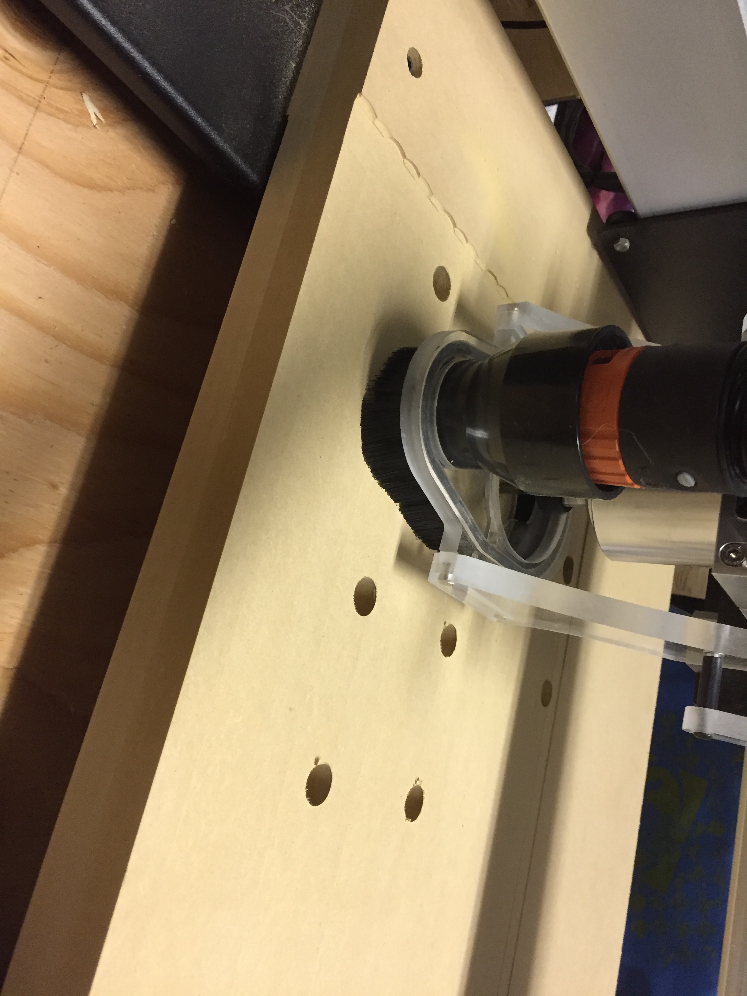
I recently posted photos of my setup here (hopefully linky-link works):
2 Likes
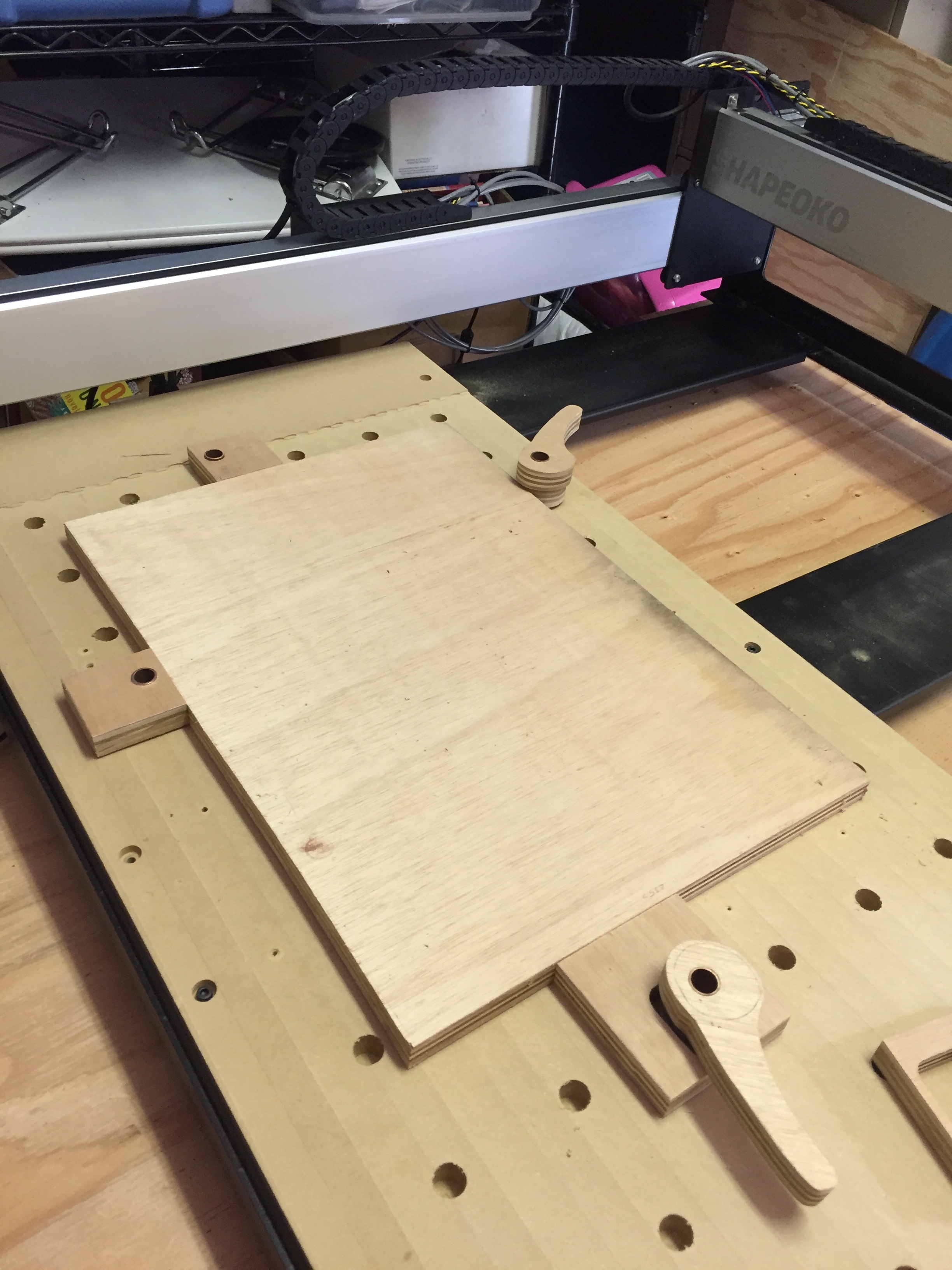
Finally, this is all coming together.
I made the clamps that Marius Hornberger (check YouTube ) designed and can finally make the rest of the jigs needed to start a clients project. In the included image you can see a plywood board that I plan to cut to make the right angle jig to complete the setup.
2 Likes