When one goes thru determination of GRBL calibration factors, is it better to calibrate using the inaccuracy/deviation of a smaller step (within reason that’s practical to measure) or a larger step?
In running this out I’m also getting some small drift of position during exercising (specifically I’m starting with Z). This is about .001" over a number of up/down jogs.
Larger should provide more accuracy — the only potential problem should be uneven belt stretch (which I believe indicates a poor quality, damaged, or failing belt).
Some folks have done it by quadrants and found bad belts thereby.
Larger was my inclination too. Thanks for the confirmation. I’ve also found that a few iterations end up with better results over larger movement spans.
Iterative refinement requires one takes the (newly measured delta) * (current calibration) you calc’d up in prior measurement run…
My depth gauge gives an inch of travel, and I’m running these iterative calibration ratios over 0.9". Effectively I engage the feeler .050" and jog in 0.1 increments
How about a tutorial Jim. But you could probably make a full length feature film without the main characters and plot lines. Seeing what you are explaining is difficult for us never been machinist types. I think I follow you but at what distance is my problem. Sorry I can’t help, good luck and hang in there. Jude
So after lots of machine jogging I’ve settled with an initial set of calibration offsets. I ended up performing several iterations of motion back and forth across my measurement span to make the final tweaks.
From this collection of movements for each axis, I refined the calibration iteratively 3 times and that was my final setting (for now, that is).
My Z-axis was the most out of whack which wasn’t a surprise based on the play projects I’ve done so far. X and Y were dang close and now they are even closer. Thanks also to Carbide 3D support for sending out a Z-belt tensioning screw and sticker SWAG. It arrived today so I could finally get this done.
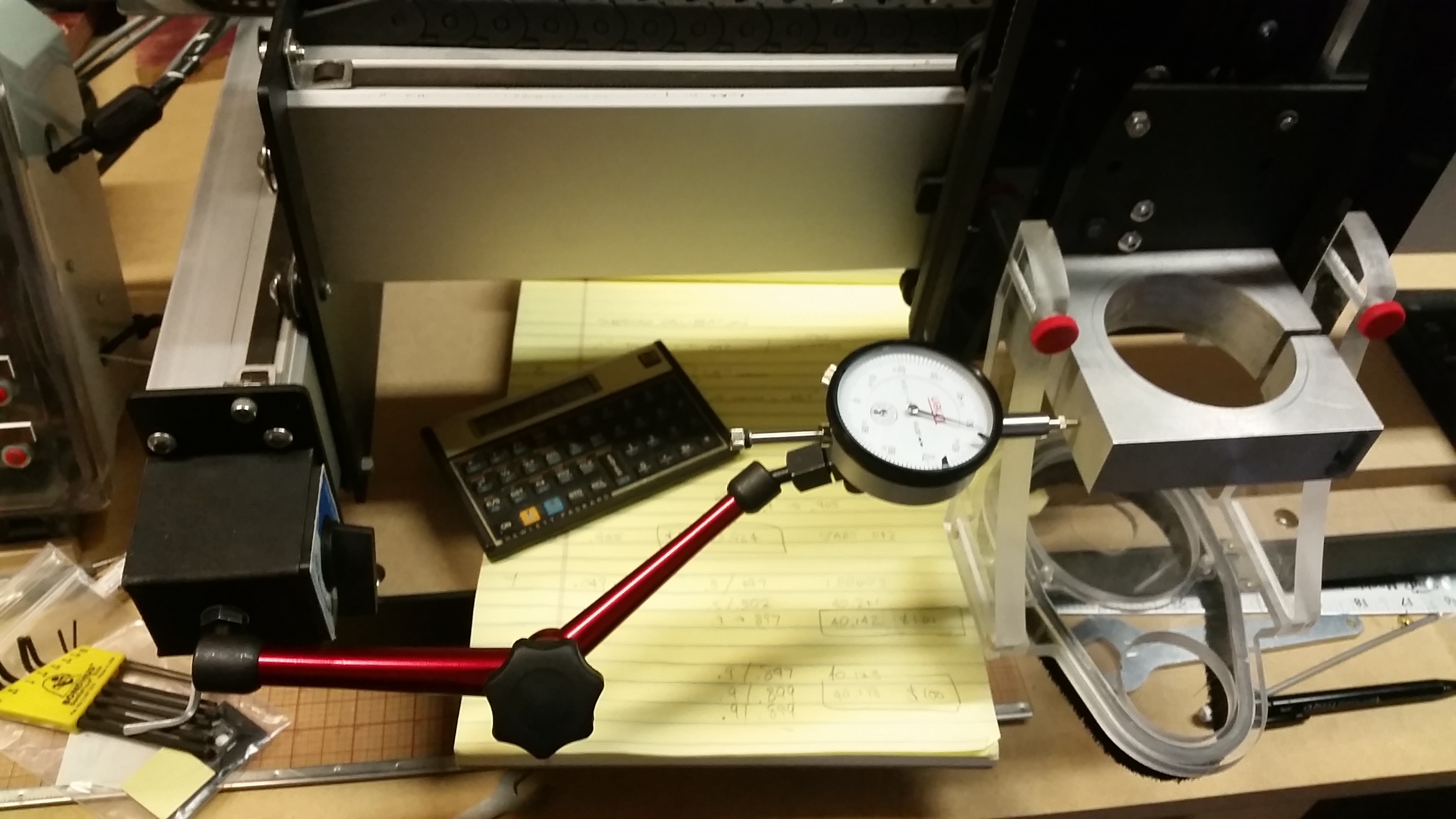
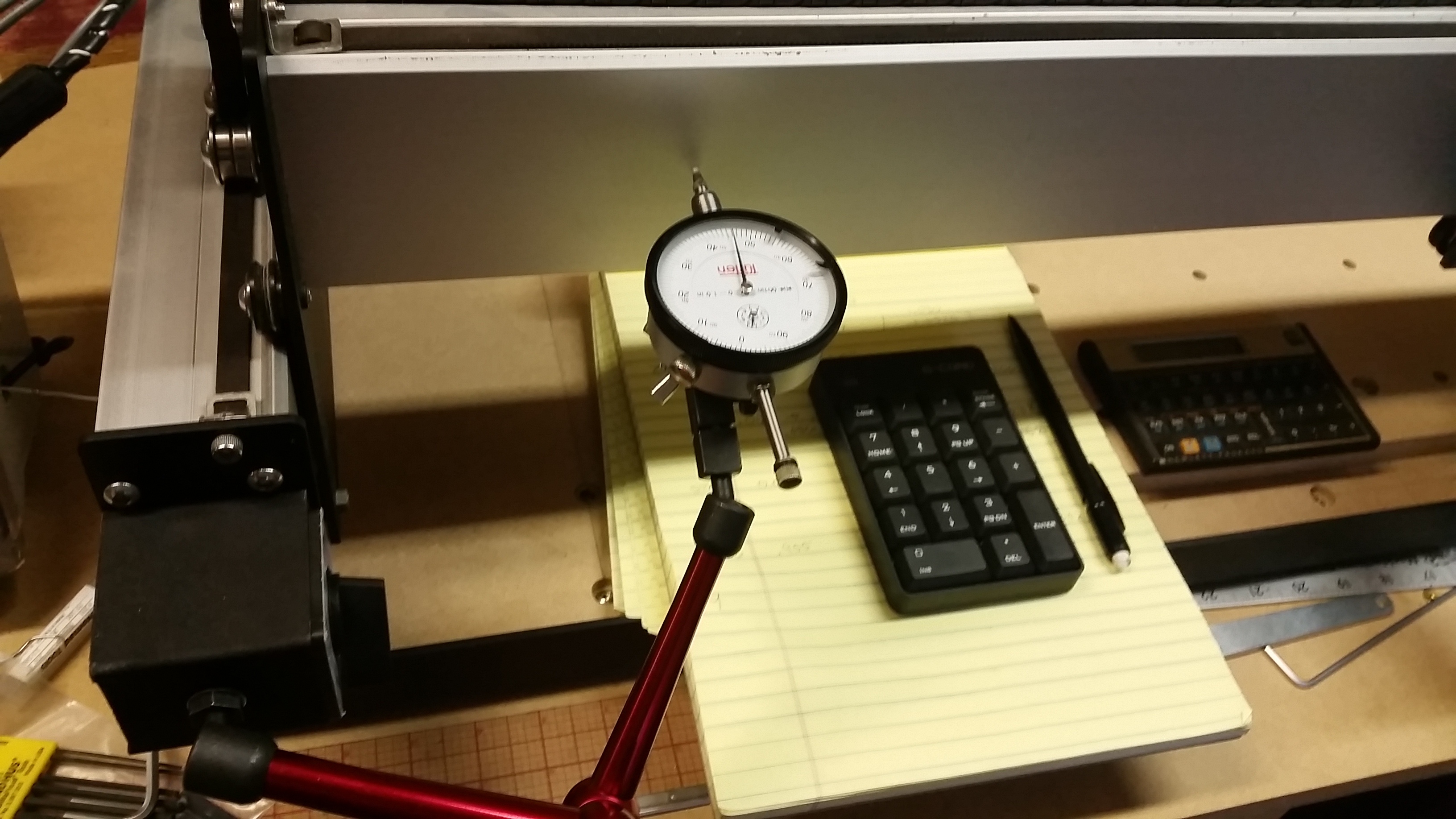
I used my existing Turlen dial with the magnetc stand linked in Winston Moy’s YouTube calibration video. It worked out nicely for X/Y as there’s lots of metal for the base magnet. The Z attachment was a little trickier as the SuckIt boot commandeers a lot of carraige real-estate, but with exact position it stayed on (I was too lazy to remove the dust boot attachment).
Tutorial? My wife tells me I’m the worst teacher in the world.
Procedurally, it’s the same exercise as shown in the link above, except instead of multiplying by 40.000 (the default for GRBL) you multiply with the calibration value you calculated and entered previously.
That’s what worked for me at least to produce the best results overall.
So to tie a bow on this thread, now that I’m calibrated with a surfaced wasteboard, I felt it fitting to finally apply “stripes” (stickers, that is). The Carbide stickers came today, and I also donned the “Suckit” sticker too. Now when I post pics there won’t be question as to what mode CNC router I have…
well done Jimi,Hoping to break the dial indicator out soon myself.Keep in mind depending on what you find with tramming that the surface board may need surface attention again.
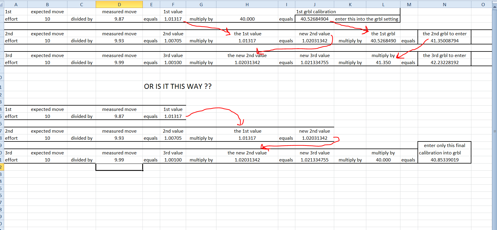
Sorry but here’s your chance, I think I did that and the new value kept growing. It does confuse the heck out of me, my problem not your explanation. I have a picture of an excel spreadsheet that hopefully explains my dilema better than my words.
The “measured move” values are made up, but do you multiply by 40.000 the 1st effort and continue OR do you only enter the last calibration? Maybe my problems are bigger than I think (too many yrs in the gas plant inhaling fumes).
It just seems to grow exponantially and why I gave up and accepted what I had.
I hope this doesn’t dismay you, it really is my problem understanding what you are obviously clearly stating. I have to be doing something wrong. Thanks Jim.
True… I trammed it for the initial surfacing and fully realize after the next exercise that another pass may be in order. I’m thinking about a widget to assist with spindle tramming…
Jude - Using your example I did method 1.
Method 2 is missing a resultant entry of the new calibration value.
I ended up homing in with very satisfactory calibrations. As mentioned above I opted to pre-load the dial at .050" as a “zero position” then I moved it 0.9" total with 0.1" jogs (using my 10-key bluetooth).
All 3 X axes produced very consistent and repeatable results under .005" which is about what I was expecting. X &Y were most repeatable @ .897" Y and .899" X with a 0.9" jog.
WOW thank you Jim, very excited about this discovery. Thank you again. I will use my spreadsheet to calibrate now using it and will report my success. Estlcam has a micrometer setting in the basic setup page. If I get adventurous I may try to locate a micrometer and calibrate to micrometers. Now that would be precise. Thanks again and off I go…
You’re welcome. I wouldn’t call it a discovery, rather just a by-product of observation. There is some level of backlash in all the movements, but when I jogged back to my zero on the dial it was spot after repeated cycling.
Calibrated today, I made 10 1mm moves in X and than 10 back measuring with the DI and I was off by .0011" on the return flight. The Y was off by 0.001". That was pretty close to start with considering I only cut plywood and you can’t measure plywood to the thousands anyway. But the first run thru got me better. Tired and will recheck the axis’s tomorrow but I did cut a circle, square test and the circle was perfect the square was too big by 0.004 in X and too small in Y by 0.011. Anyways Thanks Jim for the help.
I didn’t want to intra-convert your delta’s as it appears you’re mixing imperial/metric? As @WillAdams suggests, look at your delta’s over a larger distance. 10mm is on the smaller side, but should still net the end result required.
yeah, mixing imperials and metrics, estlcam is set up in metric and the DI is imperial so I converted in excell part way across the formulas. Why?? cus I can… But I changed the Z axis belt today because I couldn’t get repeats and after 10 moves left and back 10 moves I was off by 0.0009 inches. I left the calibration alone. Calibrating the X &Y last night worked great. Perfect circles and now the Z is good too. Very happy with your help Jim, thanks a lot. I will double check over a long distance tomorrow.
For laughs, I quantified my Z axis movement data from earlier today, I made 10 1 mm moves left and 10 1 mm moves back, after adding the moves together and taking an average it appears my Z axis is off by 0.00000013 inches. I think that quantifies as “spot on”. I ran the cal’s twice but now I can’t remember what I did… So I’m sticking with my results, no sharing of the data as ymmv…I’m happy…