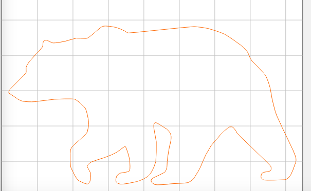
I’m a newbie, and I’m lost. I’m trying to create a toolpath for this bear with an “Outside / Right” direction, but it won’t allow me to. It only shows it being able to with a “No Offset” direction.
It’s a very small working image, about 1" x 1"
Is it because it’s so small? Even when creating a very small tool it doesn’t work.
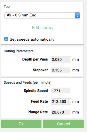
Here’s the toolpath setup. The tool is based off a tool I found on eBay (have not purchased yet because I don’t know if it will work). See anything I’m doing wrong?
Well that screenshot shows it as allowing you to select the Outside right option. Perhaps it’s as Will suggested in that the path might not be closed. What does the simulation show?
The simulation doesn’t show a cutting path. Is what you mean by the path not being closed, does that mean I didn’t complete the bear outline to be a solid bear? If that’s the case, how do I close the drawing path. I do see there is a small break in my lines, but they won’t connect completely.
OK … the path cannot have a break, it must make a solid object. What program did you use to make the picture of the bear? Perhaps you could post the file (svg). It should be easy to close the path but it will depend on what program is used and how familiar you are with it.
@JaredHooper Well that explains a lot! Thank you Jared. I created the bear in Carbide Create, with the contour tool (not sure if that’s what it’s called, I’m at work now; can’t upload the file since I’m at work too). Is there a way to close it in Carbide Create, or should I draw it in another program first? I do have Gimp, I imagine that program can handle it.
Also, I am a complete newb to CNC, just received my Nomad last week. Sorry you have to deal with me, hehe.
Here’s an svg version of your bear that I quickly redrew. Try loading that into CC. You’ll probably have to scale it to the size you want.
This forum wouldn’t let me directly upload the svg file … says it can’t determine the size??
Anyway here’s a link to the file on my dropbox, you should be able to download it from there.
If you’re going to be making more drawings that are similar to cut or engrave you probably should get the free drawing program Inkscape and learn how to use that. It’ll be daunting at first but there are lots of online tutorials and videos to help.
@JaredHooper & @WillAdams & Anyone
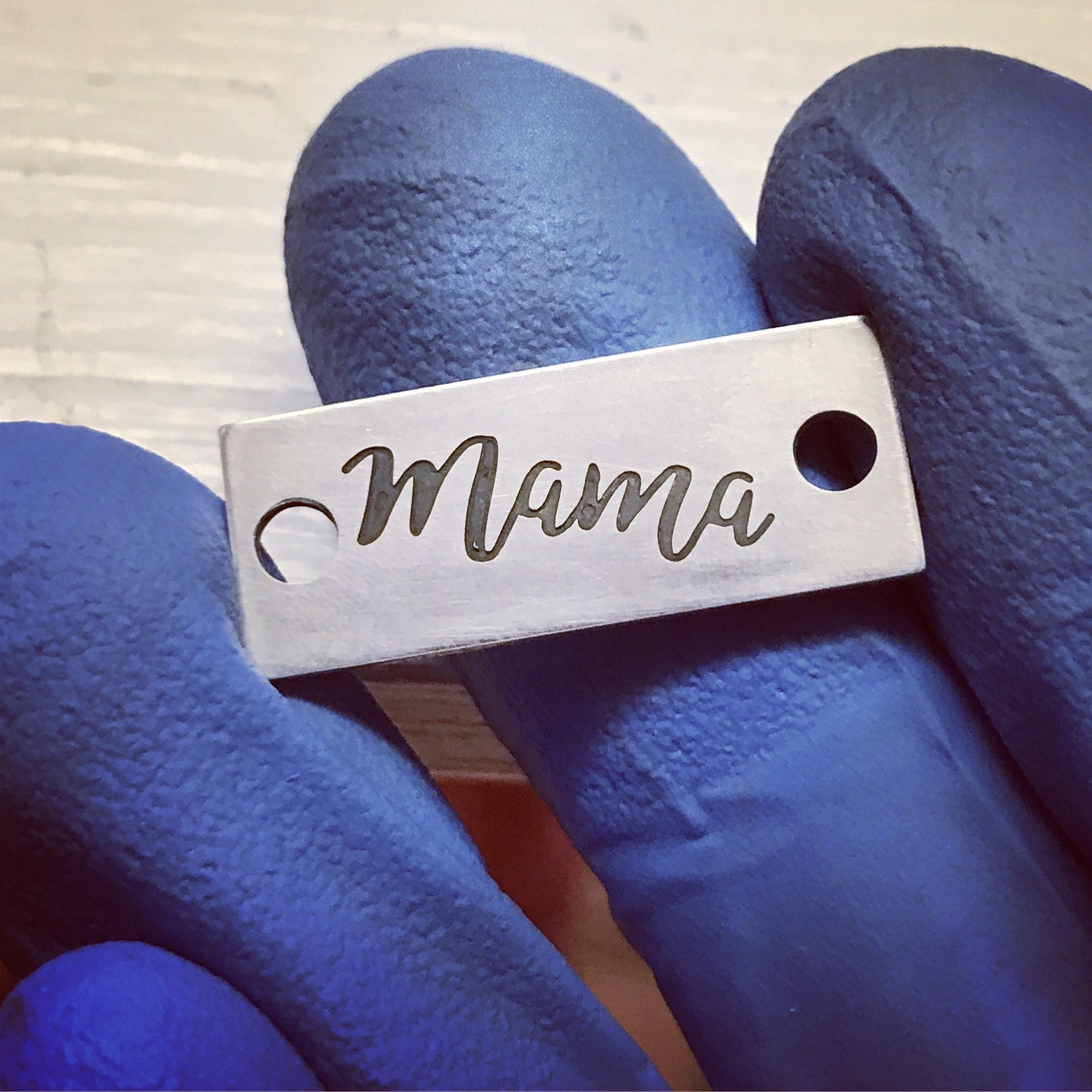
So, I finished my very first project, not even close to what I planned. The original plan was to have this “Mama” inside the bear design, and the “Mama” was to be cut through the stock piece of Sterling Silver. I broke the first bit halfway through, bit size .0118" end mill. That’s okay, figured I could work with it with the bear still.
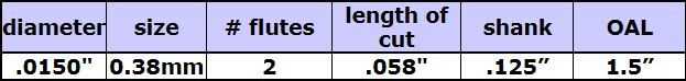
Then, I broke my second bit on the bear (.015" or .38mm bit)
I think my problem was the feeds and speeds, but I’m not sure. I let Carbide Create set them automatically, but I think it moved the bit along the X and Y axis too rapidly for such a small bit. I probably should learn a little more about speeds and feeds first. Do you think this was the problem? I’ve attached the settings for the bear cutout with the tiny bit…
That’s a pretty tiny bit for doing a cutout. I imagine that you’re trying to save silver, but perhaps you’d be better off with a big bit and save swarf and bits?
I don’t cut any silver, but for Aluminum, CC is always wrong (for me) by default.
@markwal Thank you. I’m not really trying to save the silver in this case, just trying to learn. Down the line, yes, I’ll be more worried about saving. I used such a small bit for the cutout because the bear is so small, less than 1"x1" so the detail would be gone with a larger bit.
Is the Feed Rate the speed at which it moves along the X and Y? Cause I’ll have to play with that number if I get more bits this small.
I believe @ApolloCrowe will be better able to help you on this — alternately, have you looked into getting the CNC Cookbook G-Wizard calculator?
I really wish that we’d just license it for inclusion w/in Carbide Create and MeshCAM (apparently there was a nifty integration with it and MeshCAM a while back which is currently broken?).
FWIW, there are some feed and speed settings at: https://www.shapeoko.com/wiki/index.php/Materials and at some point I’d like to work up a way to clean up that page and list more data in a more user-friendly fashion — probably the ideal thing would be some sort of database which would use a chip load calculator as a front-end and display specific settings when available.
I also started in on collecting specifics for the Nomad at: https://www.shapeoko.com/wiki/index.php/Nomad_883#Feeds_and_Speeds (but will probably leave only the official chart there, and move anything else to the Materials page — single point of control and all that.
Assuming you’ve got a good hold down strategy, maybe you could do the cutout twice. Once with a big bit and then again with the small bit. Rough then finish. Problem is that you’re still gonna have full engagement in the inside corners which is where you need that small bit, so you might not gain anything from the stronger bit.