Just ceated my first test product for my new XL and ran it, and have a problem with one of the tool paths.
It is a simple job I created with CarbiteMotion, has some letters which I chose to cut using vcarve, and a polygon border that I chose to make a pocket cut.
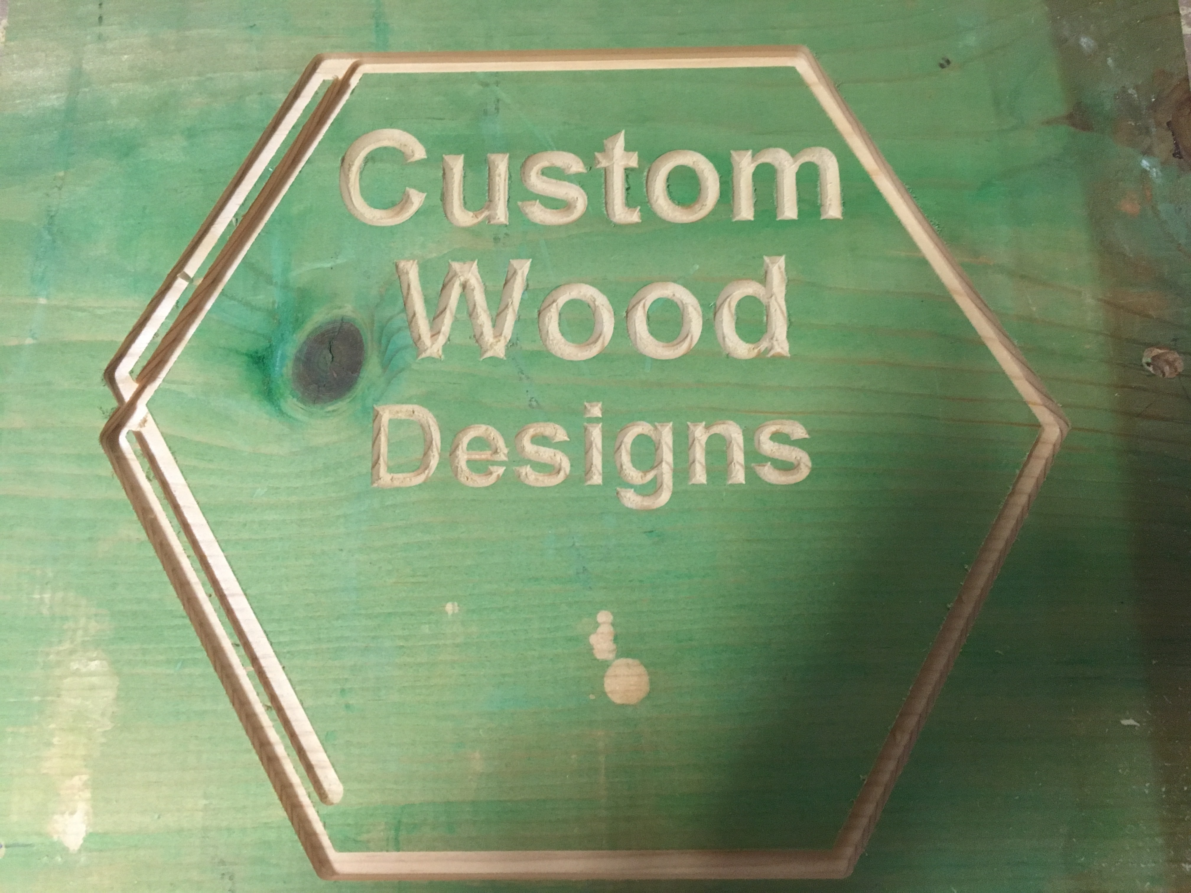
Looking at the drawing in CC, it looks OK, but when I run the project it puts an extra cut on the left side of the polygon. I wrote a whole new CC program, and it does the same thing
It does the letters OK. Attached image shows what I am talking about.
Slotting is difficult. Unless it was exactly the same paths cut wrongly, my suspicion is insufficient belt tension and the endmill getting grabbed by the sides of the slot.
Check the belt tension and change the outer profile to a pocket cut by adding offset geometry to make the width you’re cutting at least endmill diameter + 10%.
Y movement, so I assume if you locate the center of the work mdf waste board, the router bit should be able to move 8 1/2 inches backwards and 8 1/2 inches forward. Mine is not doing that. With it jogged towards the back, it just barely goes past the center of the mdf. With it jogged all of the way forward, the router bit is way out past the front rail of the machine.
I had the board I was cutting centered on the mdf, and the problem was that as the router started moving toward the back, it went as far as it could go and then it made a noise like the bit had hit a knot or something and then it turned right and started cutting across the horizontal top of the polygon. It wasn’t able to move far enough towards the back to finish the cut before it turned to the right to cut the horizontal part of the polygon. Does that make sense???
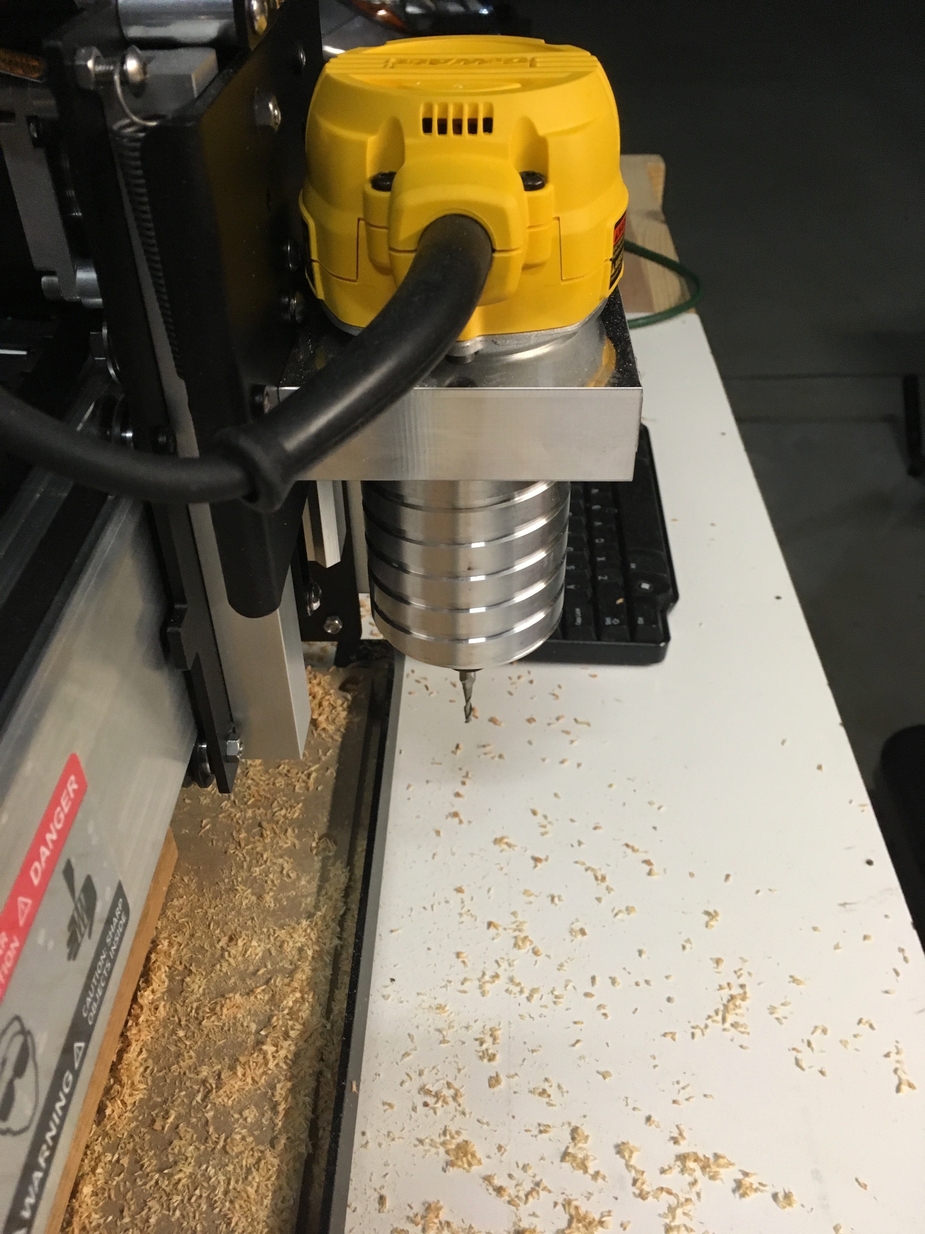
It is because the router is not able to move far enough towards the back of the machine, and it moves too far towards the front of the machine. You can see what I am talking about from the attached photo.
I thought I must have assembled something wrong, but looking at my machine and comparing it to the photos in the assembly instructions, I can’t see where anything is wrong. I attached a photo of my machine so you can see if you know where I went wrong. Correction, it said I can only put one photo.
(optional) Traverse the working boundary of the job as a final check.
The machine working area is a bit thorny — I think the most compleat writeup of it is on the wiki:
Cutting Area (note that this includes a 2 3/16" overhang area at the front of the machine)
Metric: 425mm x 425mm (note that Carbide Create limits this to 406.4 x 406.4mm)
Imperial: 16+" (X-axis) x 16+" (Y-axis)
XL: ~33" (X-axis) x ~33" (Y-axis)
XXL: ~33" (X-axis) x ~33" (Y-axis)
If you need a supported work area, some users have chosen to added a projecting spoilboard — the intent though is to make bit changes easier, and to allow one to cut things which are too tall to fit on the machine otherwise, esp. the ends of boards for joints.
Hopefully this helps — please let us know if you have any other questions or difficulties.
So your saying the piece of mdf you supply is not the actual total working area of the machine? In other words, I can’t center the piece of wood I’m working on on the center of the mdf, but rather I need to put it further towards the front of the machine.
If that is true, then to get the full 17" cutting area, I will need to have my workpiece actually hanging out over the front rail. Since the rail is higher than the mdf, I would need to add some more mdf to the top of the supplied mdf to get it above the front rail and then put another mdf on top of that in order to have a level work area.
Am I reading your answer right and what I said above is correct?
Yes, that is correct. Good point about the rail, I’d forgotten that. Lastly, please note that you need to have some safety margin for the soft limits and the home/limit switches endmill diameter will further reduce effective cutting area as well. I think those’re the last wrinkles.
I jogged the router to all four corners of travel and marked them so I would know where the work area was, I put a new piece of wood in and ran the program to cut the polygon and it worked perfectly.
The mdf is 5/8 inch below the front rail, so I think I may cut a piece of 5/8 plywood and put it under the mdf so a workpiece can extend out over the rail if necessary.