and the lualatex/metapost file can now read in the JSON from OpenSCAD and interactively create the beginnings of the box:

and the lualatex/metapost file can now read in the JSON from OpenSCAD and interactively create the beginnings of the box:
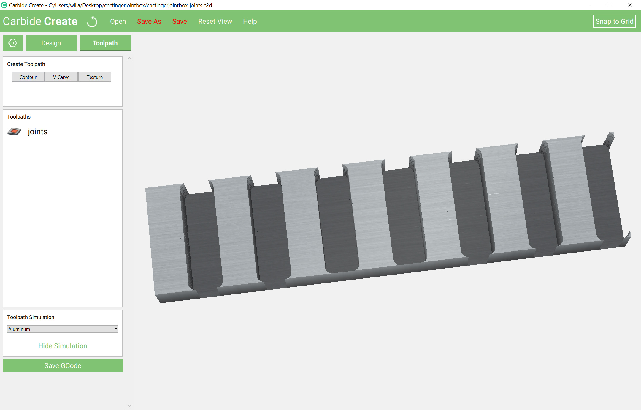
and it now draws in the cutouts for the joints:

which just leaves adding in the divider(s), labeling the parts, colour-coding the paths, working up the fixture and writing up the documentation, including how to do it all by hand in Carbide Create.
And it now draws in a divider:

Drawing this up by hand involves a couple of pretty straight-forward cuts.
First is cutting the stock to size — how to approach this is dependent on whether one is using sheet goods or an oversize board (in which one would do a profile cut around all four sides) or a board which is the correct size (in which case one would mill a fixture to hold the stock in place and just make cuts (with manually added tabs) at the ends.
Since the former is easy, we’ll focus on the latter. With a box height of 4" we need a pair of rectangles each as tall as the box height, the first as wide as the length, the second as wide as the width, and spaced appropriately.
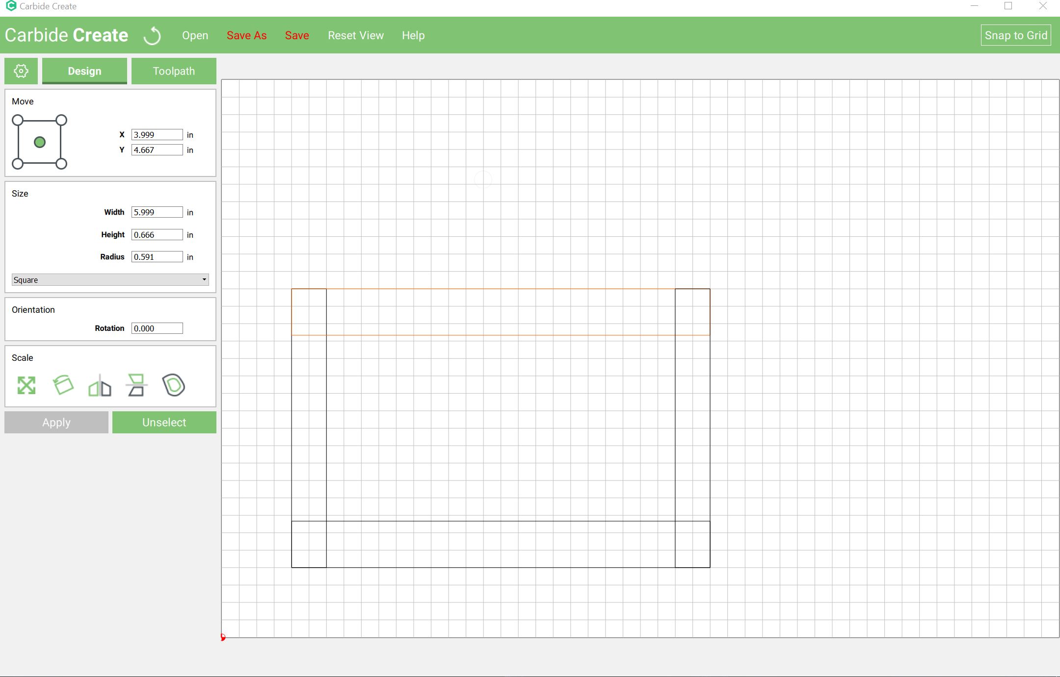
Using Carbide Create the easiest way to do that is to draw rectangles, scale each to the width or length and then arrange them to form the rectangle:
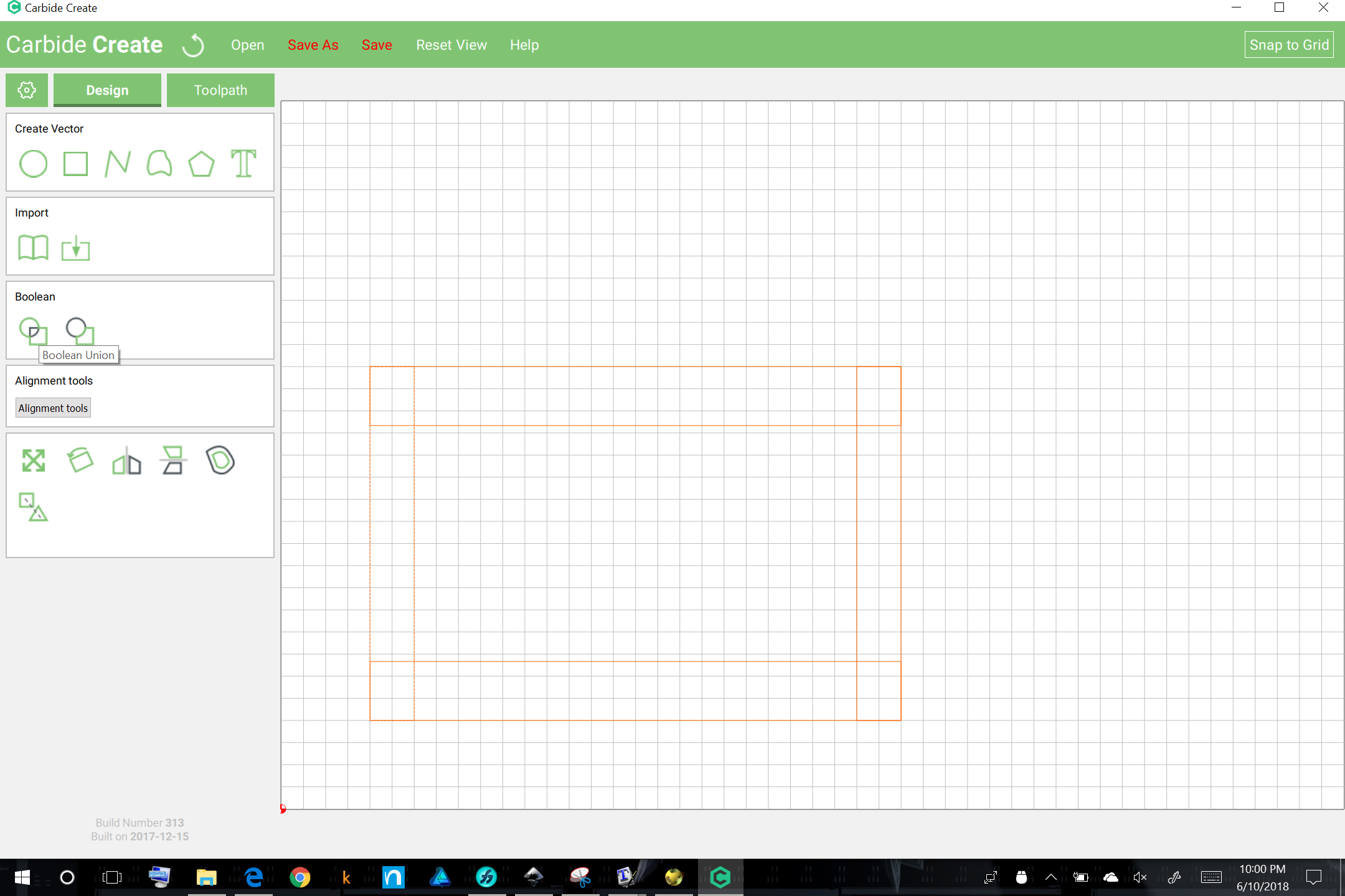
Select everything and do a Boolean Union:
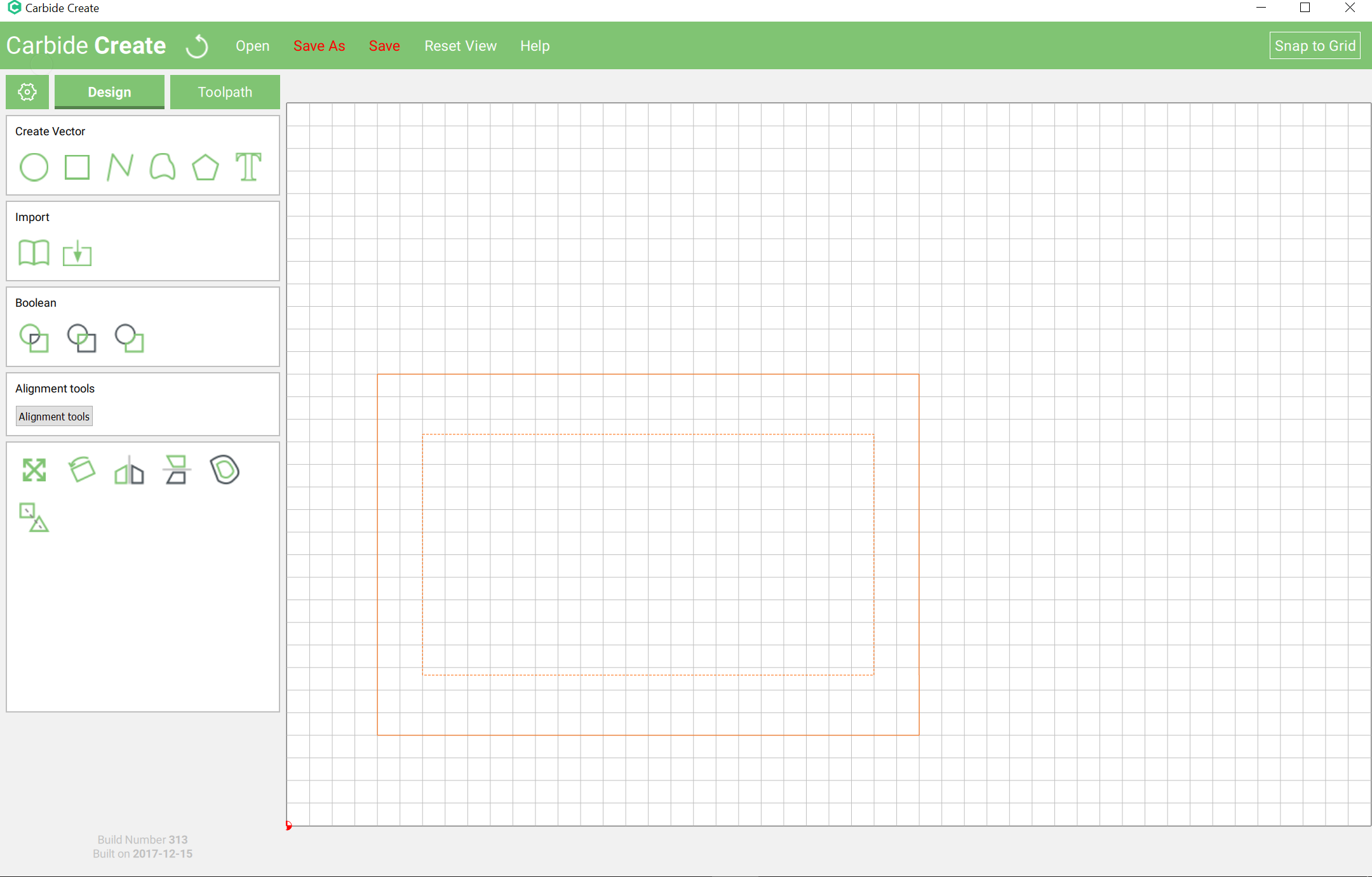
and then delete the inner rectangle:
Repeat for the other rectangle.
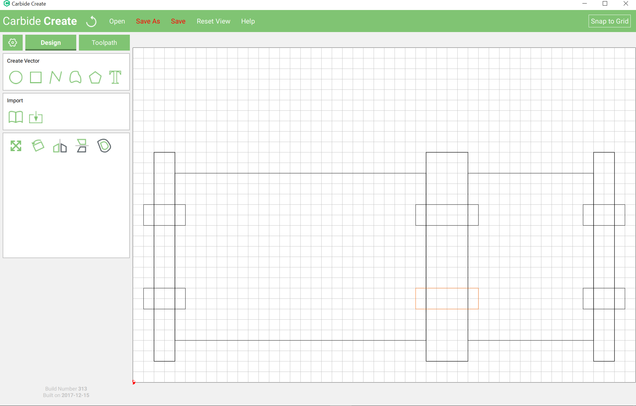
Once you have a pair of rectangles, draw in rectangles at the end, then additional ones to use to cut out tabs:
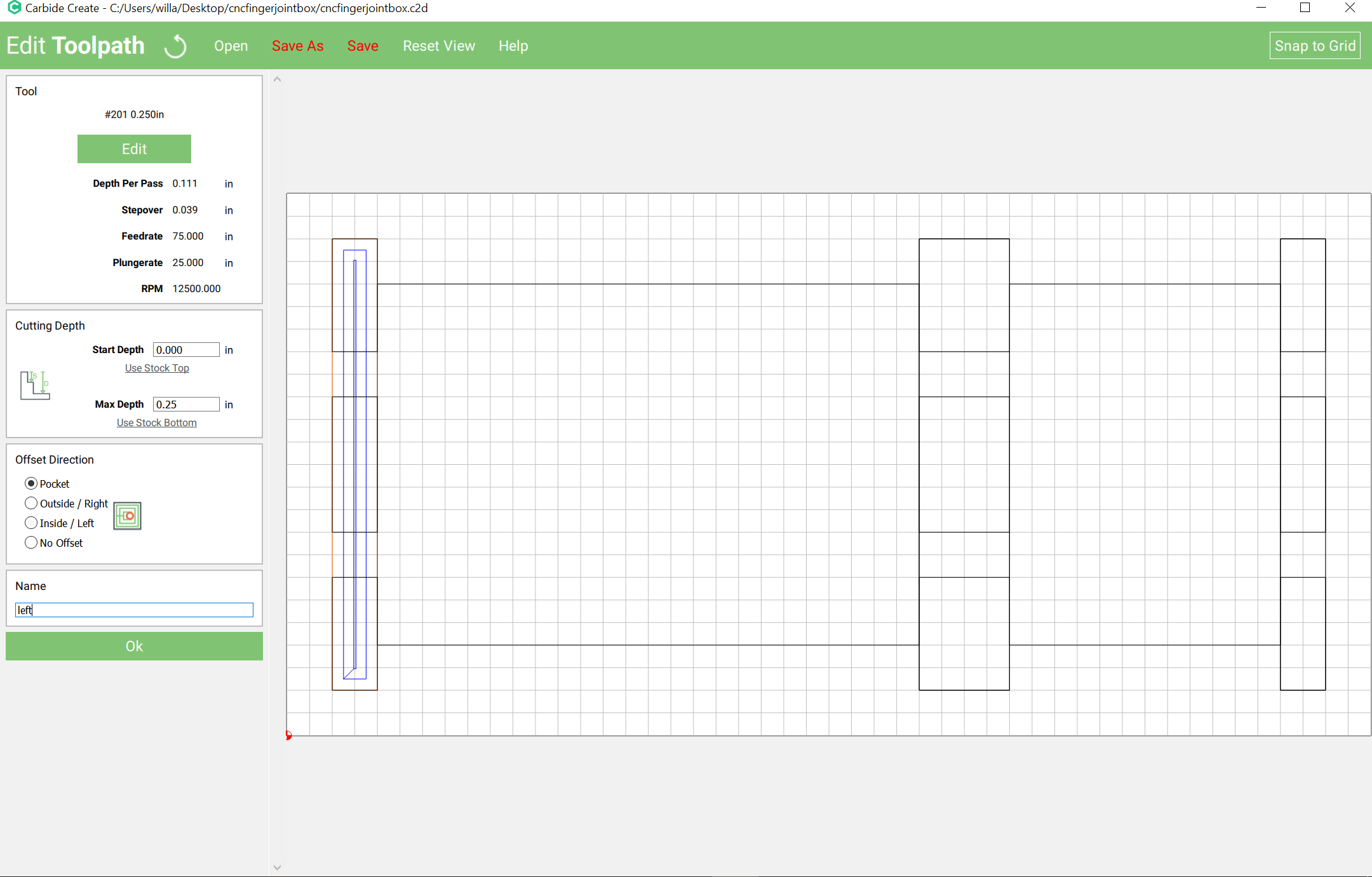
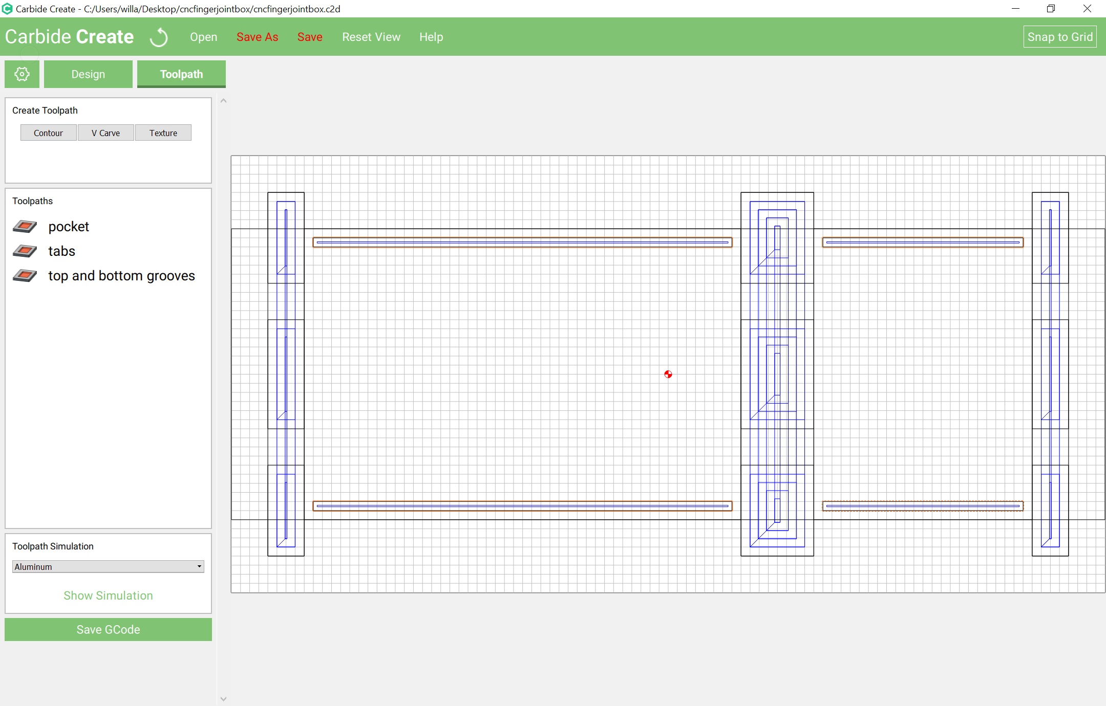
assign a toolpath to the full rectangles to cut to a depth which leaves the tabs:
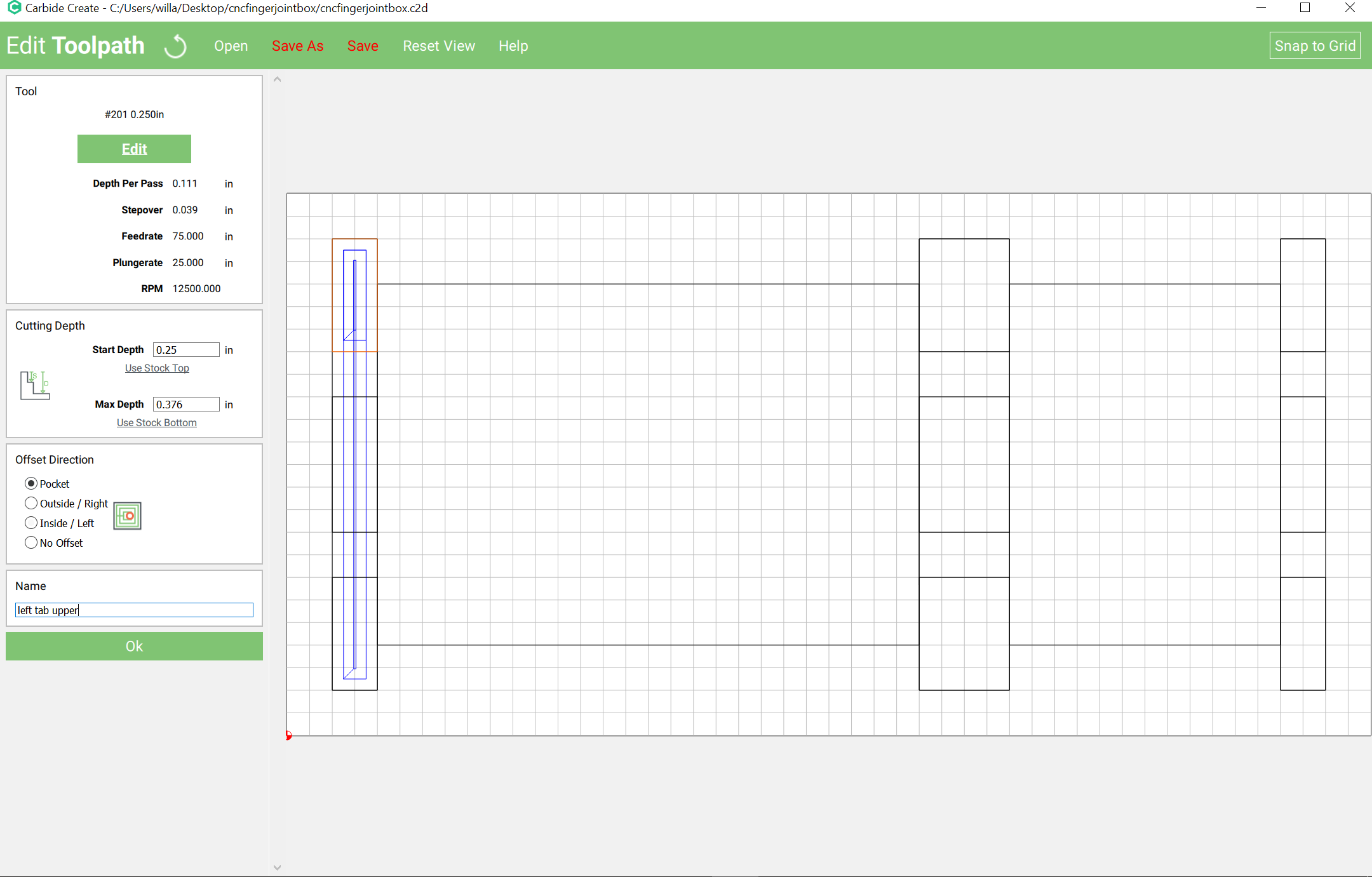
then select each partial rectangle and assign a toolpath which starts at the bottom of the pocket and cuts down past the thickness of the material:
Repeat for all the others.
Draw in a rectangle to serve as a fixture and mill it to a suitable depth.
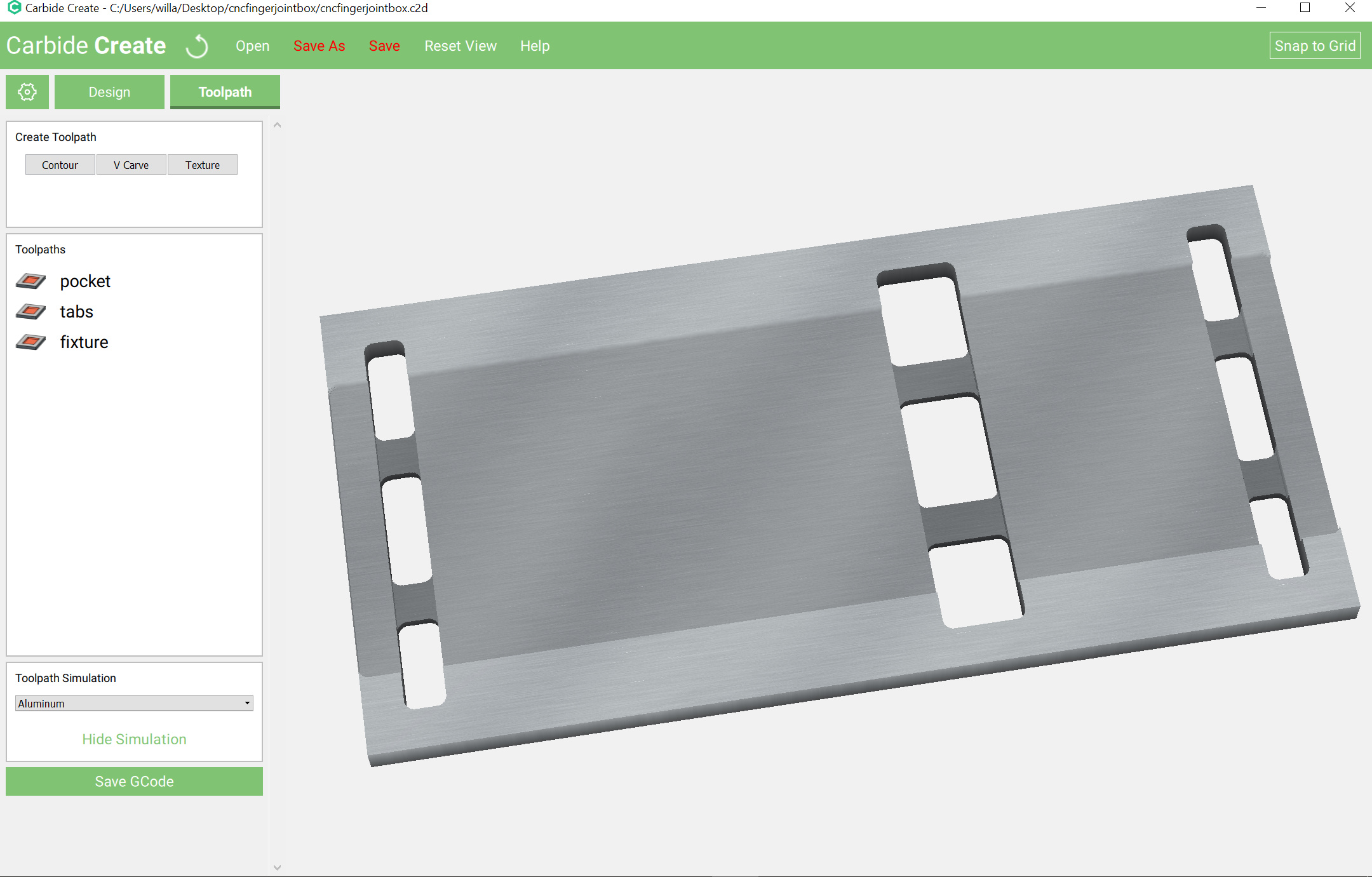
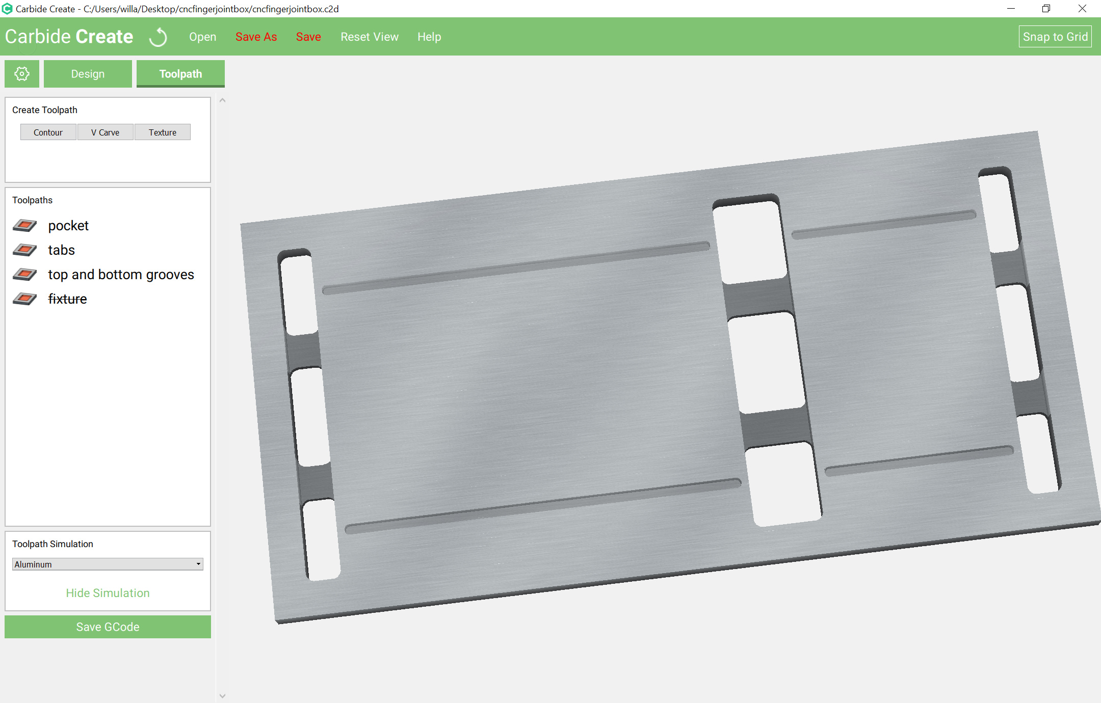
Preview to see:
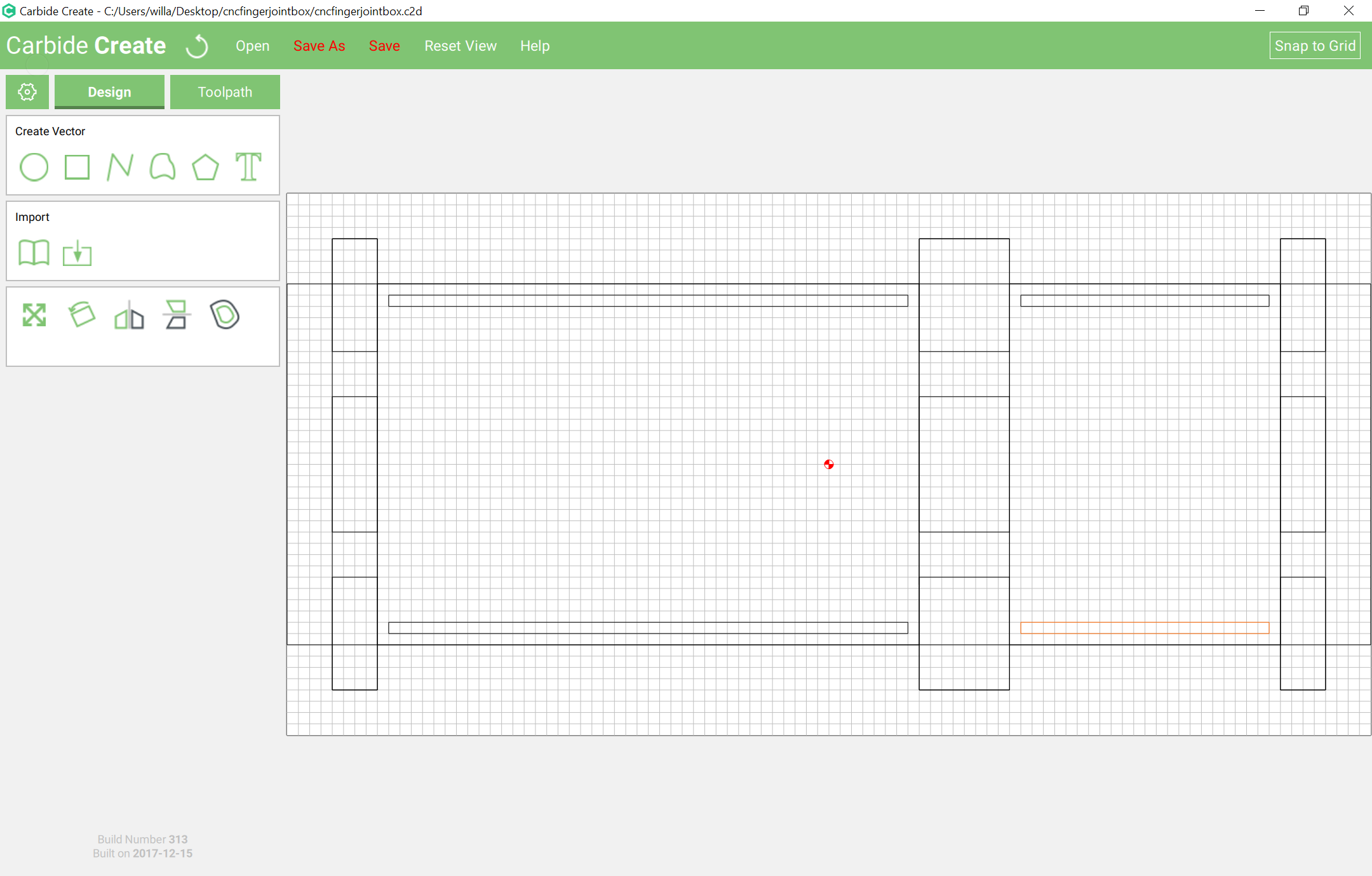
Disable the fixture preview and draw in the dadoes / grooves for the box top and bottom:
Offset the paths to the outside sufficiently to allow them to be cut as a pocket, then assign a pocket toolpath to the endmill diameter:
which previews as:
cncfingerjointbox.c2d (84.0 KB)
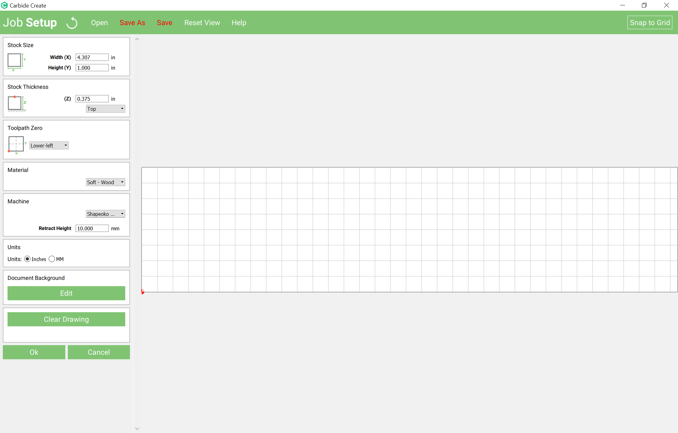
Create a new file which has a stock size which is box height plus pin height (where pin height == box height / number of pins) wide and is thickness * 2 + diameter or more in height (we’ll use diameter *2):
4/13 == 0.307692308
Mill a fixture which will hold the two boards spaced by pin height at a right angle at the front of the machine.
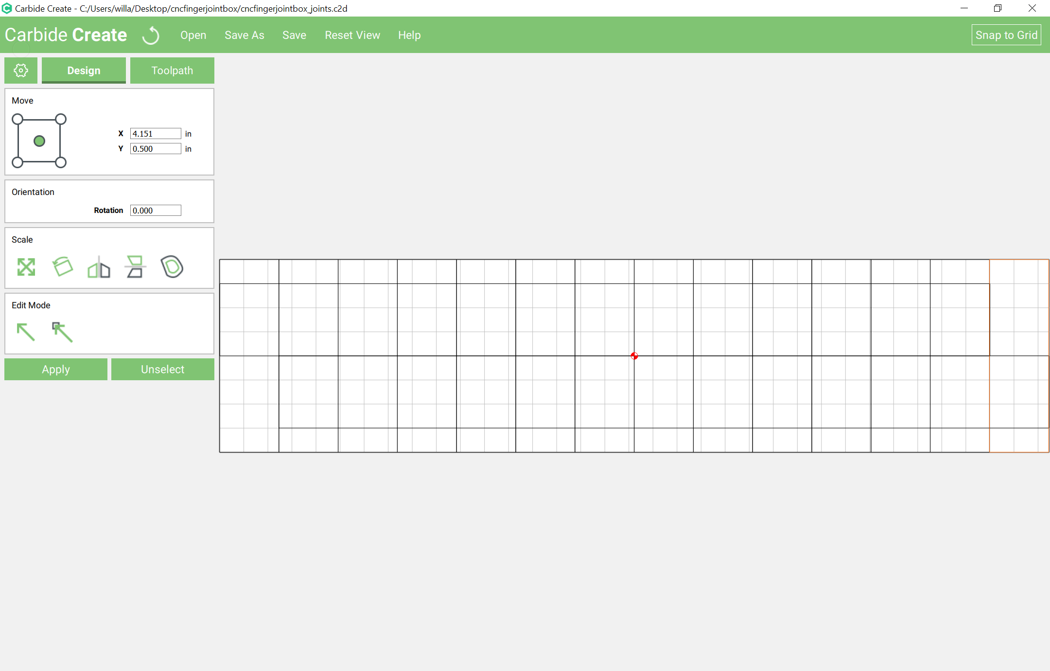
Then cut a series of rectangles which are as tall as the stock and pin height wide spaced out by pin height — the easiest way to do that in Carbide Create is to draw # of pins +1 adjacent rectangles which are appreciably taller than the stock height, group them, then scale them to box height + pin height:
Select every other rectangle after the first and assign a pocket cut to the board thickness:
Cut out two sets of parts (front/back and left/right) and arrange them in the fixture and cut the pins into them.
cncfingerjointbox_joints.c2d (31.9 KB)
It will also be necessary to cut a top and bottom out of a suitable sheet thickness material at a size to fit into the grooves. This is left as an exercise for the reader.
The LuaLaTeX METAPOST program now draws in the dividers and geometry to cut the rabbets for one sort of lid:

Is The box joint program ready to Download and run.
I see here there are 2 places to download 1 at 84.0KB and 1 at 31.9KB
Do we need all of the screens shots to understand how to make it work.
Or will there be a video on how to do it.
Jeff
The OpenSCAD file is the interface — download it and run it to select options and get a 3D view of the box.
The .C2D file is a manually created sample box.
I don’t have the lualatex/metapost file ready yet, and I suspect folks would find it troublesome to run — at this point it’s more of a proof of concept — I’m investigating other options and will hopefully have something workable presently.
If there’s a particular size box you’d like to see, let me know and I’ll post the SVG for it.
Will the boxes I want to make are 9.5" wide 7.25 “high 3.5” deep
After downloading the 2 files I will need to reference the screens that you have posted here Right?
Thanks Jeff
I guess I am a little confused, as to where you stand with the program.
I can not find The OpenSCAD file is the interface — download it and run it to select options and get a 3D view of the box. Will there be a program that you will input the height width and depth and thickness and size of pins and the program will do the rest. Then you will choose the cutter to use for the tool paths
Jeff
You have to:
Then you’d need to generate and export each part as an STL and work out cutting it if you wanted to just use OpenSCAD and the 3D model — I’ll generate an SVG as quickly as I can.
Here is an SVG which should match the instructions above:

A couple of things which this has revealed:
I’ll see what I can puzzle out.
Will, when you are done with the dado /box/finger joint program it all going to be part of CC or will we need another program to set up sizes and then create a file and import into CC to create the tool paths with.
Jeff
Currently it’s a pair of files to process in two separate programs:
I’m looking into what would be involved in having a Python (or other) program which would directly generate a .c2d file which would be ready to go.
The other possibility is a Kickstarter to set up a web site and publish a book of similar designs — would folks be interested in that?
Have there been any more up dates yet.
Jeff
Back to this — I believe the best thing to do is to cut the boards a bit long, say 1/8" at each end, then use a fixture to hold all 4 boards on end clamped to the front of the machine — I believe if each pair is aligned as it will be when the box is assembled any variations should cancel out.
The fixture should have a pair of pockets for the hardware arranged to be on the center of each pair of boards, and additional features to fix it in place on the machine:
Suggestion for the hardware: cap nuts and threaded rod.
the boards should be supported at the bottom by a board a bit narrower than twice the thickness of the boards which will be used capped off by a spacer as thick as the additional dimension added to each end — it can be placed for the second cut so as to lift the boards up to the same Z-zero.
You’ll want a set of clamps to clamp the boards to the front of the machine. I believe these will work:
Alternately you could grind down a set of clamps to fit.
The program for making the SVGs will need to be adjusted to double up the boards so that all 4 are cut at once — that should get this box down to 3 setups: first cuts boards to rough length and mills in features, the last two machine the finger joints into the ends.