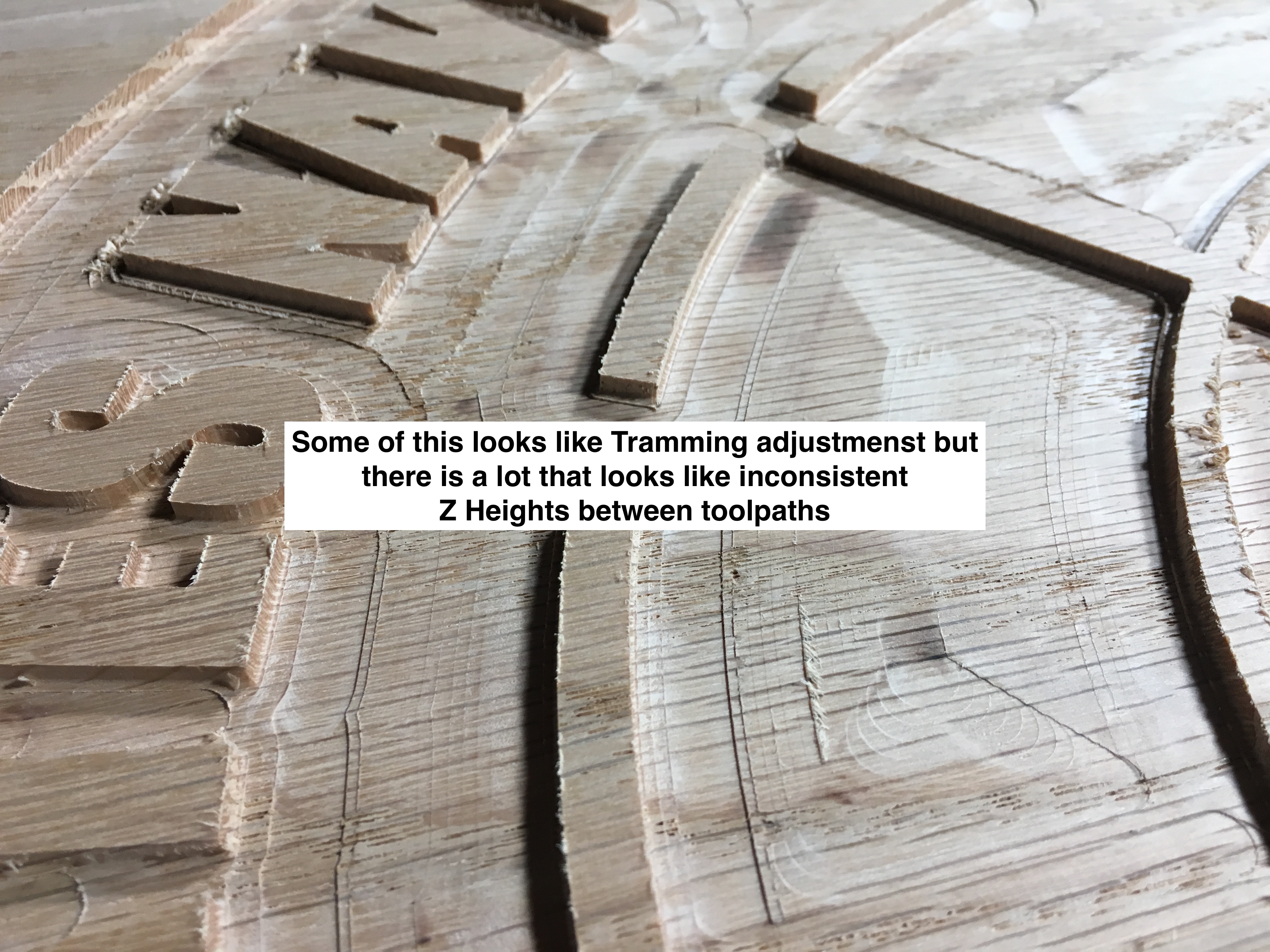
I am looking at my recent projects and I am a little concerned about the quality of my pockets and the inconsistencies along the pocket floor. I thought maybe it was showing I need to tram my dw611, which it may need some very minor tweaks. What I am looking at though doesn’t look like a tramming issue though. I checked the set screws and they are all tight and on flat notch. Belts feel tight enough though the info on tensioning these is not precise so it seems subjective as to whether I am correct in the amount of tension. The V wheels are all snug and there is no slop on XYZ carriages when I check them.
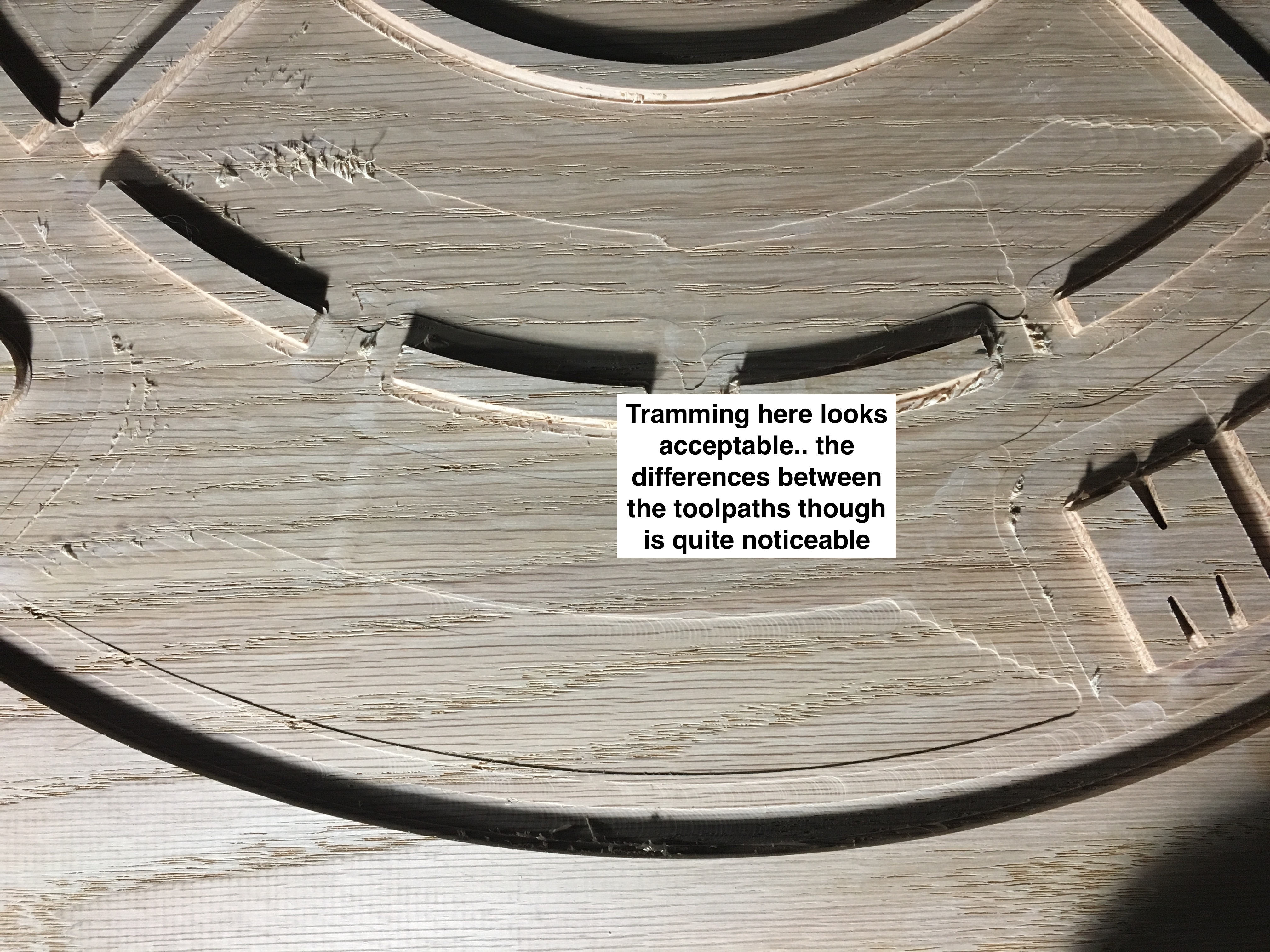
When you compare the results between the Z floor of my pocket cuts to my relief cuts… it is night and day. The relief cuts look beautiful… better than anything I ever expected to see. The bottoms are as flat as can they can be. This got me thinking that it might not be adjustments that are required. Considering how many times the Z height changes on a relief carve it really seems like the machine is tuned and accurate.
The images will show you what I am seeing. The Oak job is going to be tough to salvage if not impossible. The entire pocket area will be painted so I might be able to make it work but I am thinking it will be a nightmare to try sanding/filling the height differences. I suspect I will either have to run the job again on new blanks OR run it again on these boards but drop the depth by about .04".
Before I do that, I really need some help figuring out what might have gone wrong. I thought maybe it was the OAK blanks and some inconsistencies in them. But as I started thinking about that it can’t be the answer. Even if the boards had a pronounced cup or variable thicknesses, the floor of the pockets should have still been smooth.
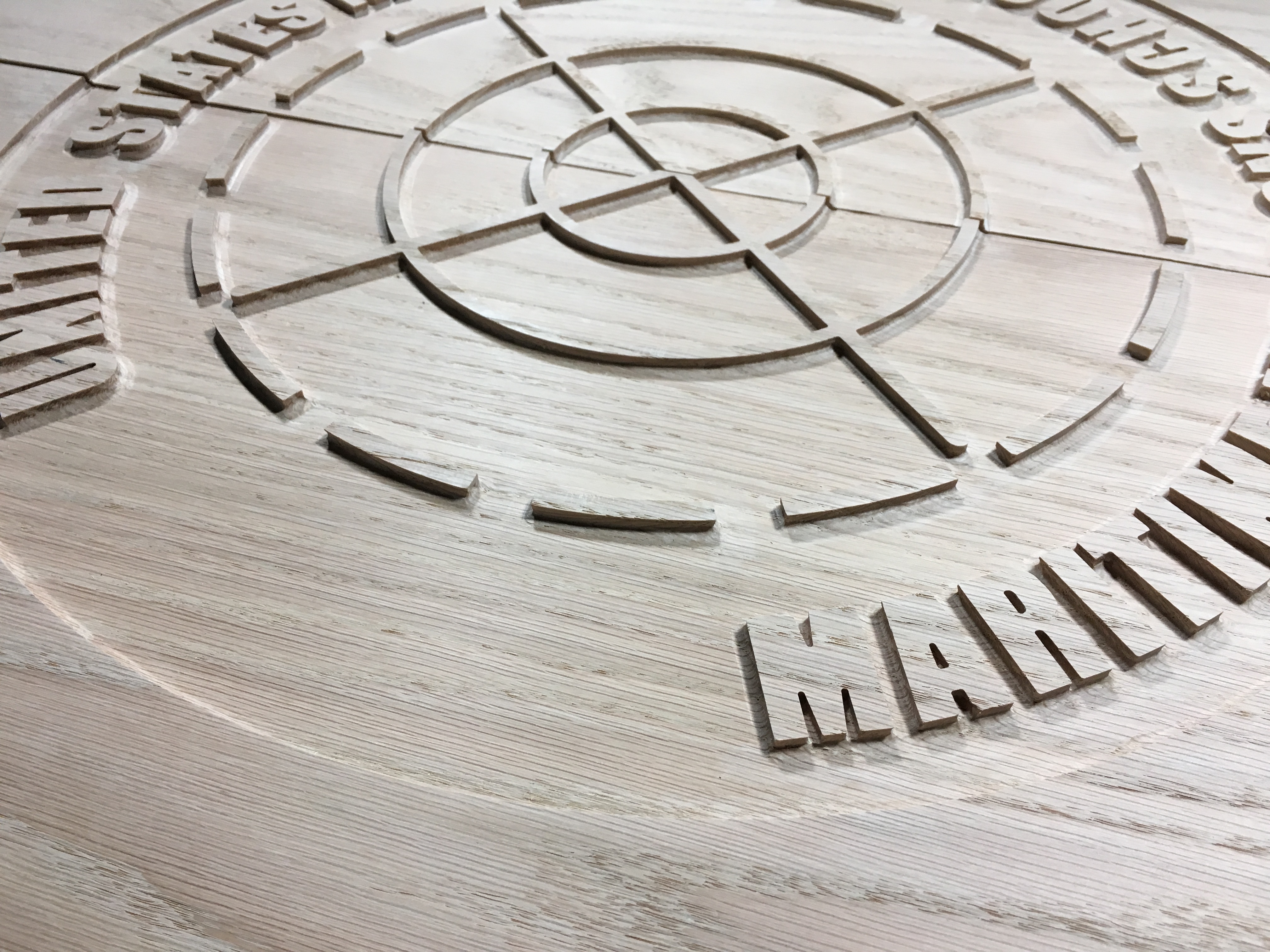
Feed Rate was 25ipm with a cut depth of .125 for the oak project. Spindle speed of DW611 was around 2 on the dial. Step over was about 20% if I recall properly.
John I don’t know the exact cause of your issue, and I agree that looks really bad and would be hard to fix. One possibility to fix it would be to try to run a ball end mill along the same toolpaths from the same X-Y zero, but with a really small stepover, like say 5% or less of the diameter. Also, I notice you are getting some burning on the wood, so I wonder if some of this could be caused by moving too slowly? Could the end mill be pulling on the wood and flexing it? Could the wood be flexing or moving on its own? I think you have both a tramming issue and something else going on. I also see that around your letters, its like the toolpath didn’t do a proper contour, maybe from trying to use too large a tool? As a final note, I also used a white oak for a small sign one time, and I had similar issues, though not as bad, but that was probably a function of scale. I was using Fusion 360 at the time which doesn’t handle text or graphics well, and haven’t really used it for that kind of stuff since. I wish I could be more help.
I don’t believe the wood was flexing… It was screwed down with 4 screws. I visually inspected the boards flatness to the wasteboard before starting the jobs up because I knew i had a very slight cup in the blanks.
The job was run with the .25 EM for the clearing pocket and the .063 BN was used for getting in between the letters and the tight radius in there. The .063 toolpaths look very nice. It’s all the .25 tool path that was a mess. I don’t think I over-tighten the collet but I certainly don’t under torque. I briefly considered bit slippage but I don’t believe that was the cause.
Speed/Feed rate could likely have been too slow. I heard some chattering on a previous job in OAK with a .125 deep pocket and I ran that one around 40ipm.
I thought maybe adding a texture tool path might help salvage this… then again, I might just spend several hours of machine time just to decide it’s unacceptable and it needs to be scrapped.
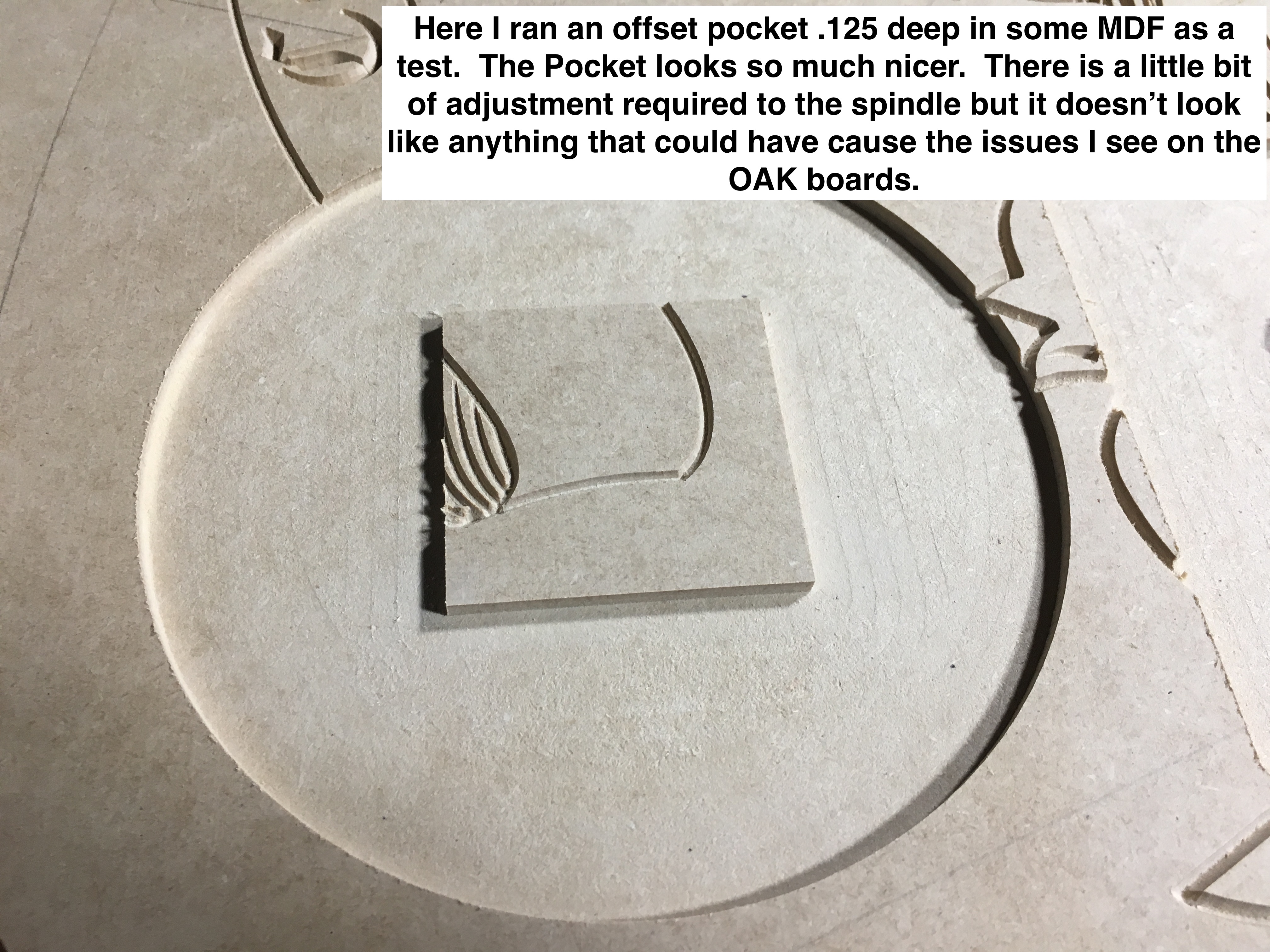
I am going to run the existing tool paths in a piece of MDF with the feed rate boosted up to about 40-50ipm and see what it looks like… If I get acceptable results like I did in the MDF test images, then I’ll be left wondering still why this happened, or I’ll have to assume the minor imperfections of the Oak blanks was the cause ( even though I still can’t picture how it could be ) . Either way, I am pretty concerned about running this project over in a set of oak blanks until I have the issue diagnosed and fixed.
For what its worth, I was running a project yesterday with some slotting cuts at .1" DOC, in Ash (as notoriously hard as it is) at around 66 IPM @ 21000 RPM, and I even sped it up on the fly to about 80 IPM just to push it a bit. I like CM4 for this, because I can adjust speeds on the fly. What I’m noticing is that my standard feeds and speeds are ultra conservative, and probably shortening the life of my tools.
A texture tool path would definitely work, particularly if is one you can cut with a V-bit.
1 Like
Griff
(Well crap, my hypometric precursor device is blown…)
5
I had an issue similar to this last year, I cut quite a bit of red and some white oak too.
In my case, the screws that secure the router to the Z plate had loosened up. With the machine on, so the steppers lock, grab the router and see if it moves at all.
Thanks for the input! I am pretty sure I had checked this ahead of time. Yesterday I actually pulled the spindle out of the Z carriage so I could more easily check the V wheels. They seemed pretty tight when I loosened them but I will keep that in mind as I try to run this again…
I think I might rerun the job on the existing boards but with a .0625 BN and just go to a depth that will flatten out the pocket bottom… it’s going to take a lot longer to run but I am more confident in the results I will get.
I plan on definitely running some more scrap oak and just cutting in some random shaped pockets to try and see what I can do to improve the results.
You’re right, looks pretty rough. Here are some ideas:
Look at the endmill under magnification - some of the places here it looks like it tore the wood (left side of img 2361) and pulled the grain right out instead of cutting. That shouldn’t happen.
If the endmill doesn’t look perfect, obviously replace it. You must use magnification to do this, don’t rely on your mk1 eyeball. Look for chips at the tips of the flutes.
You must have multiple tool paths here to be able to cut inside the letters (“M” for example) - is you’re Z-zero method really solid? This can’t have been all with the .25" mill.
If it’s not that, you’ve got something rocking, somewhere. Be sure to check -all- the eccentrics, not just the Z carriage. If any are wrong out on the y rails, the whole x axis can rock back and forth and left and right under the right loads. This has that “lots of backlash” look to it you get when something in the machine isn’t rock solid.
I had almost the exact same issue creep up on us last year. Check all tolerenceon your machine, clean it well, clean and tighten all vWheels.
What size of endmill are you using for your pocket?
Is your endmill sharp?
Are you climb cutting?
IMO .125” is too aggressive in oak to expect a clean pocket with the machine. Try shallower cuts, increase feeds and step over until you find what works for you.
Try to use raster tool path for clearing, appears you are using offset.
if you want a really fine surface add a last pass of .002” - .005” in your toolpath.
Using VCarve the tool paths are pockets with a .25EM for the clearing path and the .0625BN for getting into the tight gaps. I just use the method of dropping the bit down until it pinches a piece of paper to the point that is can just barely be pulled. However, when it came time to ZERO the smaller bit, the ZERO spot on the wood was already removed ( I use CENTER X/Y ) so I had to jog it over an inch or so… I don’t think that would be an issue but it’s probably not the perfect method.
I have a magnifier down there for painting small details and I’ll examine the EM but it is relatively new and hasn’t been dropped or run into anything.
I had checked all the carriages and wheels for any looseness after running the first door… everything is really solid feeling. The one thing I didn’t check is the Spindle mounting plate that is screwed in through the back of the Z plate… I’ll check that today.
I ran a 1/8" ballnose on those same tool paths last night and it cleaned up the project. I have thoughts that maybe I’ll keep using a ballnose for clearing of pockets and try to stick with a raster path rather than offset. Not sure why I chose offset over raster… didn’t really think it mattered.
Thanks for your input! I will start examining my bits between jobs rather than waiting. l
SO far, I think the one thing I learned so far is I really don’t like using an end mill for creating a nice pocket. At least not the way I have been creating my tool paths so far. I will experiment some more with reducing the d.o.c. to lighten the load on the spindle and I will try to use the RASTER method whenever possible to reduce changing the direction the cutter travels in the wood so often as the offset method does. It takes longer to raster out a big pocket but the results seem well worth it.
Honestly, I hadn’t really done any research into why/when I should use an offset over a raster strategy… I will now. I have been checking the machine for any looseness in the carriages and the spindle plate prior to every job and to me, the machine has felt very solid… The spindle can be ever so slightly flexed back and forth, parallel to the Y rails, so I will double check those spindle mount screws that attach the mounting plate to the Z plate… It is very slight though and I think that is just the normal feel and the best I can expect given the way the spindle mount is designed.
I appreciate all the help! Really. I’ll keep checking everything and making adjustments and run some more tests on some scrap wood to try and better understand how to avoid these poor results I got this time around. At least I was able to salvage the job with a light pass using a ballnose bit. It’s still going to require some hand work with the dremel in the tight areas because I wasn’t able to exactly nail my original ZERO mark on the doors since the marks were removed with the original pockets… I didn’t run the .0625 bit around the letters because I noticed I was off a few hundreds of an inch. That got me thinking that I need a different way to re-reference my pieces on the machine table should I ever need to come back and add/fix something in the future.
That’s why I made my touch plate 5” long, if I need to span a pocket or cut for my zero point. You can also jot down your machine coordinates,jog over and zero.
In VCP you can also set your zero reference to the machine bed.
@Ton80 I’m not sure what you use as a gcode sender, but I’ve been playing around with a macro for CNCjs that allows for a tool length offset probe. Your case is one of my exact uses for it…when you carved away your Z0 probe point. Basically the macro compares the lengths of the tools and applies the necessary offset for you. I haven’t had time to make a proper video (I need more hands, and my wife won’t stand in the garage long enough when it’s cold), but I did a quick write up and caught a video of the pocket being carved after the tool change.
The project was salvaged by running the pocket with the Ballnose bits I have and setting the pocket .04in deeper. Some additional time in the shop with the dremel/flex shaft and carbide cutters cleaned up the tighter areas around raised areas. My placement of the boards wasn’t perfect on the second run and I didn’t want the tight profile work to be off ( I’ll need to work on a better strategy for placing a board down in the exact same place next time.)
Thanks again for all the advice. I am still not sure exactly what caused the sloppy results but I am going to chalk it up to too deep of an initial cut, inappropriate feed rate and using an offset path instead of a raster path. The machine was thoroughly checked over and everything is solid and there is no slop in any of the carriages.
There are two things that I’ve seen that can cause this. The bed/waste board of the machine will flex, causing inconsistent depth. If you put a dial indicator on your spindle, and set it up to measure between the spindle and the bed, you can push down on the bed with just a finger and see nearly a millimeter of movement. If you are cutting soft wood with a small bit, the z axis force is quite low. When you move up to the bigger bit and cut harder materials, the required force to cut goes up substantially.
The other main thing I’ve seen cause this is the z axis skipping steps on the belt. Again, only shows up with harder materials and bigger bits, as the forces go up so much. If your bed and spindle are set up to where the spindle needs to operate very close to it’s lower mechanical limit, this skipping problem seems to be worse. I had to remove one of the return springs from my z axis in order to reduce the forces to something tolerable by the belt.