This is my first real design in Carbide Create. I am working on learning both it and Fusion 360. I’m not really asking for help in doing something, but I would like for someone to please take a look at my .c2d file and see if it makes sense. If anyone is wondering why I don’t just copy or download one of the existing designs, to that I say that believe learning to use the design software is just as important to me as learning to use the machine. How could I understand why a project went wrong if I don’t understand the underlying design?
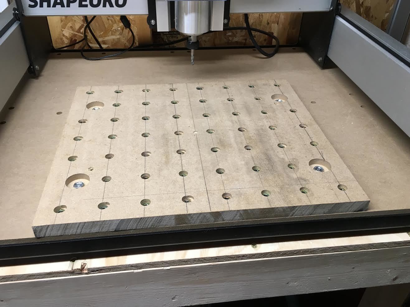
I designed the threaded wasteboard in Create because it seemed simple enough to design. I want my stock S03 to cut all of the holes for my threaded inserts and to countersink the bolts that will hold my wasterboard down to the stock base board.
My stock size is .750" x 16 x 16 MDF.
I am using 1/4-20 x .511" (13mm) tall threaded inserts so I designed the holes for the inserts to be .266" in diameter, which is the recommended drill bit size (H) if I were to drill these by hand.
To recess the bolts to hold down the board, I made a countersunk hole that is .450" in depth (.132" bolt head height + .5" washer thickness + some waste factor to recess the bolt head sufficiently below the surface of the board). The OD
of the washer is .688" so I made the diameter of the cut .750" to give some room.
The holes are all centered on a 2" grid. Do I also have the Toolpaths correct? Threaded Wasteboard.c2d (30.4 KB)
The C2D file looks good. I usually lower the feed rate since I don’t have a dust shoe, and I’d be more than happy to look at your tool paths. Could you post an .NC file?
Will you be installing the inserts from the bottom?
Looks good to me as well, assuming your measurement and understanding of the hardware are accurate.
Some thoughts:
using the 1" grid was an excellent way to get the nice precise placement — you’ll want appropriately scaled clamps, which can reach across that up to 2" distance to match, possibly a set of them, or, do as @Luke did and make clamps which are more adjustable than my simplistic design: Nomad 883 threaded table and clamps
2" spacing is a reasonable compromise in terms of material strength and # of inserts — it also matches up well with typical stock dimension, so workable all around
the larger holes are for the mounting hardware? I’d consider putting them on odd grid marks, in-between a 2"x2" square of existing holes — that way you’re never wanting to clamp somewhere there isn’t a hole
while it’s fast and efficient for you to just select lots of geometry and tell the machine to make toolpaths, the software doesn’t take that into consideration, and will create inefficient toolpaths — for each separate bit of geometry in a toolpath, the system will
cut one layer
lift out
go to the next and repeat until the first layer has been cut in all the geometry, then it will repeat for the next layer — if you extract the plain text G-code there are post-processors which will fix this. Other alternatives include working up the code for one file, then using it and G92 (and a comm-control program which understands that) to do a step-and-repeat
Very conservative feeds and speeds — if they’ve proved out on a bit of scrap, you should be good.
Will: Okay I have some more to learn then regarding post processing, but that’s why I’m here and trying to design from scratch.
Yes, I am currently working on my own clamp design in Fusion 360. They closely model the basic clamp design (not yours in the link, but the ones where you have a “jack” screw on the end, and a slot cut in them for the clamping screw), but mine have a slot milled for a 1/4-20 allen head screw with enough room to cover 2+ inches in the slot. I want to try the same design in both HDPE and then aluminum. I’m waiting on my McMaster Carr ordered supplies to come first!
Will consider moving the larger mounting holes. Lots to learn.
I think if you select a single hole and do the toolpath just for that one, it will go all the way to the set stock bottom rather than the inefficient way. It’s tedious to do it for each one, but if it works then at least you can do it all in Create.
Part of the reason it is inefficient is because I deliberately set the tool path to in Create to mill the holes in multiple passes by controlling depth of cut. Working on learning now how to do multiple passes using depth of cut to finish each hole completely before moving to the next one. Learning is occurring…
Well, I completed the wasteboard project, although it went through some revision versions compared to my initial comment in this post. Yes it looks like garbage, but that’s okay, because I learned in the process. No big deal, because I really only abused a 2’ x 2’ piece of MDF, which is only like $8 from my local Home Depot. On that note, Lowe’s doesn’t sell MDF in less than a 4 ’ x 8’ sheet. Home Depot on the other hand has them in 2 x 4 and 2 x 2 sizes as well.
Things I learned in this process…
How to use Carbide Create and Carbide Motion
That there is no real way to clamp a wasteboard down to the existing base in order to mill out the holes
Eventually I had to just run screws through my wasteboard into the base to keep it from moving around
That it is really easy to type in the DIAMETER of a hole you want in Carbide Create when it considers it a radius, giving you a hole twice as big
That it is easy to mess up your toolpaths and think you are only doing a counter bore, when the machine is really being told to mill that size hole all the way through the stock
That the threaded inserts do need to be counter sunk / bored in MDF, you might be able to get away with not doing this in another harder material like wood, but the MDF is too soft to not do this
Knew this already thanks to a Winston Moy video, but since I plan on surfacing my board in the near future, you can’t really have a 16 x 16 supp wasteboard on a stock S03. Mine is about 16 x 14, which allows me to hit all of it with a surfacing bit. I also can overhang this board in the X and Y dimensions without worrying about it.
This board is just my “initial” one. I think I will build a v2 in the future, having learned all the points above, and incorporating them and hopefully not making the same mistakes again. All in all, not really a bad first project, and an inexpensive way to learn through trial and error
I actually described working up a way to bootstrap this sort of thing using nothing but:
SO3
trim router
1/8" endmill
18"x24" half-inch cutting board (or similar) — if the piece won’t fit between the lips of the end plates a suitable arrangement to lift it up so that it may be clamped in place levelly will be necessary
~88 T-nuts (#10-24 or similar)
3 clamps
a 2x4 or similar guide less than 24" long
suitable cauls to allow clamping the piece (need depends on clamps used)
Great job on deciding to just build something and learn! I’m sure v2 will be even better!
So the way to go is to add another MDF on top of the one you get with the kit, and do the threaded inserts on that one? For some reason I assumed you can manage with just one.
I created a supplementary spoil board for a variety of reasons on the stock S03:
The experience of designing and doing it
MDF isn’t going to give you a surface that is perfectly flat and perpendicular to your endmill
If you want to surface plane your wasteboard, as I plan to do, you cannot reach all of the stock wasteboard
This means you end up with a “island” that is lower than the surrounding wasteboard
By adding the supplementary, I can surface plane it (because I recessed all the metal hardware sufficiently) and it will give me a raised area for the “island” instead of a depression
On the stock S03, the metal edge of the base sits a small bit higher than the existing wasteboard; with my setup, I can hang over the edge if need be
Most importantly, I’m going to screw up again at some point. I would rather have a cheap supplementary wasteboard to cut into by accident, than to dig into the base