Having modded my SO3 to move the motors and gain a few inches of area over the table, I now turned my attention to the aluminum table I sourced from the eBay/Amazon seller (Carbide 3D didn’t have any of their single-piece units).
I wanted as little variance between the table and the spindle as possible. In the past, I’ve done this by making small adjustments to the position/height of the extrusions. That works okay, but my concern is parts shifting over time.
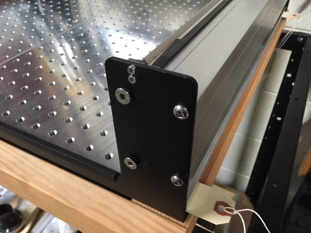
This time around, I replaced half of the screws holding each extrusion with 6mm flat-head screws. I used the holes closest to the edges on which the wheels ride, figuring that is where the money is.
No, the steel is not countersunk, and the flat-head screw sits proud of the steel a bit. BUT, the taper of the flat-head screw DOES wedge into the holes in the steel and pretty much eliminates any variability in positioning. When snugging the flat-head screws, you CAN feel the extrusions move ever-so-slightly if you hold you finger at a corner between the steel and extrusion.
With that done, I turned my attention to the aluminum table. I spent a little time with a DI mounted to my dust shoe mount, moving the z-carriage around and measuring my distance to the table. I was able to determine that I needed two of my card-stock shims at each of the three screw-hole positions at the back, and one card at the front-right.
After getting those shims added, I am within about +/- .002" around the entirety of my now-larger (due to reconfiguring the motor position) work area. I honestly think it is more like +/- .001" but I’m having a hard time believing that myself.
And I feel like I could loosen/tighten any screws necessary without having to go through a complete realignment.
I’m not advocating this method for anyone else, just sharing what I’ve done.
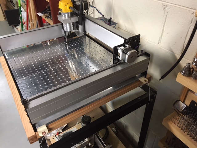
My first photo shows the flat head screws I’ve added, the second photo shows the pretty much completed rig with the aluminum tables.
And yes, I’ll likely tear-off the excess cardstock now that I’m done with my show and tell.