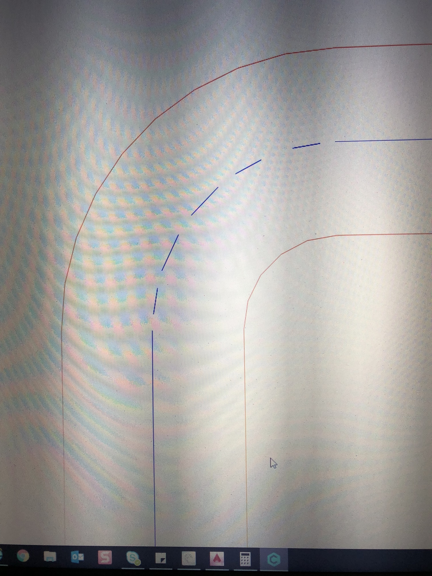
I’m trying to mill letters that are the exact same width as my 1/32” endmill. I draw the letters as closed polylines in AutoCAD and import them in Carbide Create as a .dxf file. To achieve an efficient tool path, I want each pass to fully millout my letter (not take two passes at the same depth to mill out the stroke of an “i” for example). CC sometimes has problems (see dashed line in attached photo, it should be solid line) where there is a turn in the stroke of the letter. I drew this as 0.031” diameter with the inner radius at 1/2 the diameter. I’ve tried 0.03125”, 0.0313, 0.0312” diameter and all have the same issue (dashed line instead of solid line). Does anyone know why this is happening, or how to accomplish what I am after?
Note: It is important the lettering is exact as the pockets receive inlay.
I’m no CC pro here but I think the problem you have is the curve is made up of a series of straight lines. If the width of the letter is exactly the width of the cutter, every time the curve transitions from one segment of straight line in the curve to another the cutter is not able to pass through without going over either the outside or inside line. Thus CC resolves by having the cutter retract/plunge around each part the cutter can’t fit into. If you look closely at the image you posted every retract is around a point of the curve.
Not sure if it’s a solution for you but think CC has a toolpath that just follows a line instead of being constrained in between two lines. Might work better for you.
Hi Brent,
I agree with Phil and Will here, a No Offset toolpath is what you want. You will need to manually create the centre line in AutoCAD, not use a V-Carve toolpath (Which would not give you a consistent depth).
If manually tracing the centre line of each letter seems like a chore, and you’re not tied to the font you’re using, you can use a single line font, which are designed for this application. Some are already available in AutoCAD but others can be downloaded.
And I know what you’re thinking, you’d then have the problem of creating the outline for your inlay pieces. This might help:
Convert the text to lines with the TXTEXP command.
Rather than a basic offset, you want a buffer around these lines
Then create an outline around the buffer. See the attached lisp routines.
For internal areas use the BOUNDARY command
If you don’t know about lisp routines yet, I’d be happy to give you some pointers.
Thanks for the thoughts Will. I like the idea of drawing the centerline of the letter and using the no offset feature. I could then offset the CL of the line to either side it 1/2 my mill diameter to give me a path to pocket around for my inlay. Seems like this method might work, I’ll give it a try!
Owen! Nice to run into another AC user. You sound quiet skilled I appreciate you chiming in. I’ve tried converting AC font to lines but have noticed that the stroke widths of the letters are not consistent. I like the idea of using single line font-how do I use these? I am not familiar with lisp routines but I can do some research. I’m really interested in your comments and suggestions-seems you may be able to help me be more efficient in my lettering!
I don’t know about skilled, but I’ve got 10 years CAD experience, so I’ve tried a few things.
In addition to regular fonts available everywhere, there are single line fonts in AutoCAD (Such as romans.shx), which will not display normally in most other programs. Look for “.shx”, when choosing a font in AutoCAD.
Lisp routines - you can think of them as custom commands that can be added to AutoCAD to do much more complicated things than could otherwise be achieved. So the buffer command not only offsets the lines on both sides, but adds arcs at each ends and makes a closed ployline. A fantastic source which will blow your mind is: Lee Mac http://www.lee-mac.com/index.html Enjoy!
Also bear in mind that the cutting direction will affect the finish. If you only take one pass through a slot essentially one side of the cut will be climb-cut and the other will be conventional-cut. Depending on your needs this may or ma not matter. For 1/32" grooves, probably doesn’t matter but still a good concept to understand.