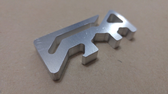
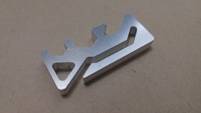
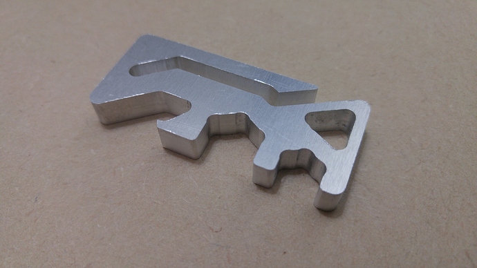
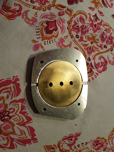
First attempt at aluminum failed, please help

Thanks everybody

The design is a “copy by eyeball” of https://www.youtube.com/watch?v=3_bSr_cBi98 but I wanted to take a shot at 1/8" end mills first before snapping 1/16" end mills, so I remodelled it completely, and without pockets

So on the next attempt, increase RPM to 10000, 0.065 inch margins, 12 inch/min feed and 3 inch/min plunge?

You should check out some of the feeds & speeds articles in here and elsewhere to determine those numbers empirically, rather than just guessing at it—so you understand the chipload and know what you’re doing :wink:

So I did look around the forum

@ApolloCrowe gives out TPS files with his tutorials, which is great, thanks, but I didn’t see one for aluminum

This guy @zymurgy here First aluminum job is using 8000 RPM 16 in/min feed 8 in/min plunge, faster than my numbers, but with a smaller stepdown and much less complicated geometry. He claimed to have gotten the numbers from G-Wizard. @ApolloCrowe call the numbers aggressive

@mitchell http://community.carbide3d.com/t/recommended-speeds-and-feeds-for-aluminum says 5 and 1 works but is slow. @robgrz suggested 10-12 for feed. @WillAdams links to the same Shapeoko page I was reading

Plugging the numbers myself into FSWizard gives me 20 inch/min feed. From all that I’ve read around here, calculator software cannot be fully trusted yet, at least not for the Nomad, and experience trumps all.

I’ve :v: hacked :v: MeshCAM to give me the Carbide Wizard option for aluminum, with the highest quality setting, it’s telling me 12.2 inch/min feed, 1.52 inch/min plunge, 0.01 inch stepdown, spindle RPM will be 7500

What do you think of those numbers?

I ran 6061 number through G-Wizard and all of those are believable.

There are many correct solutions for feeds and speed. Many are equivalent, some have interesting affects on the finish.

Reasonable roughing (rather than hogging) numbers at 7500 RPM is 13 IPM, plunge of 6 IPM. 0.015 cut depth.

I would definitely rough things first, then finish. Fine finish is 4 IPM, plunge 2 IPM.

Using AlTiN coatings adds 2 IPM to all the numbers.

mark

Frank,
I would like to suggest the 1/16 cutter over the 1/8 for waterline type cuts like this. Less material to remove.

Your posted numbers should work well and eliminate the step-out from the high plunge rate you saw in the first cut test you posted.

12.2 inch/min feed, 1.52 inch/min plunge, 0.01 inch stepdown, spindle RPM will be 7500

In early testing I was cutting 10IPM 1.5 plunge .015 step down and 10k RPM with the 1/8 cutter.
with the 1/16th cutter that i prefer now, I would slow the feed to 8.5 ipm.

I have a stack of materials to test cut on the PRO so you can expect to have a full set of tested feeds and speeds soon.

Have you tried our fixturing wax?

1 Like

The only reason why I’m avoiding 1/16" cutter right now is I’ve got a fear of it breaking, I figure I make a sacrifice of wasting a bit of time and material to lessen the risk of snapping a end mill entirely. Am I wrong?

I am using that roll of double sided tape that shipped with my Nomad. I didn’t want to mess with wax, as I am on carpet lol I wouldn’t know how to get it out if it dripped. Funny story, the first time I used hair spray on my 3D printer bed, there’s now a dark spot on my carpet where I sprayed it…

I hope I get some updated materials.csv and any updates to the Carbide wizard Lua script. I am not understanding where the “Power” column of materials.csv is derived from. I will eventually need to add my own values for materials like grade 5 titanium.

The “power” for aluminum is set as 400 inside materials.csv, but I don’t know the unit or what property it maps to. Is it tensile strength? shear? hardness? Inside the calculation, this value is used to recommend the DoC and predict the deflection on my cutter.

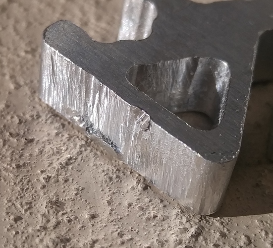
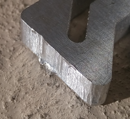
I finished the cut but the surface is very rough, any tips? I accidentally left the RPM at 7500, or perhaps it’s because the end mill got dulled up, or maybe the feed rate of 12 is too fast?


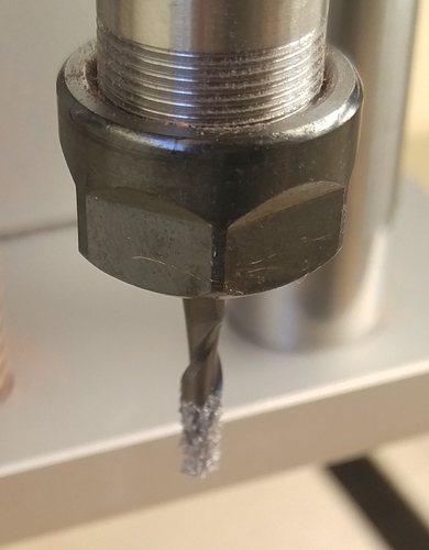
Also, how do I clean up a AlTiN coated end mill that got a bit sticky? I… uh… cut my finger on it already lol what’s the right way to do it?

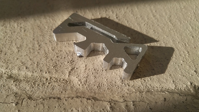
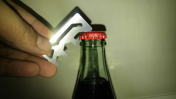
By the way, the geometry of the bottle opener is a perfect fit, but the size of this thing doesn’t have enough leverage for a comfortable bottle opener, it works, just a tad small and there’s no comfortable way to grip it

I… uh… cut my finger on it already lol

Been there. Done That. :joy:

There is no practical way a high quality end mill will be dulled in one or two uses with the materials you’re working.

AlTiN coating is not recommended for Al work - it attracts the Al being cut; use ZrN or TiB2 coating. If that end mill doesn’t clean with a stiff brush, the Al is probably welded to the end mill… the end mill is toast. Is it? If so, it also confirms that the parameters are “off”.

Could you please post the the MeshCAM parameters window?

mark

The old parameters were actually 6800 RPM, 12 feed, 1.5 plunge, 0.064 margin. I think touching the wizard overrides the RPM

I made a new cut, 9500 RPM, 10 feed, 1 plunge, and using the Carbon3D factory stock 1/8" carbide end mill, and also no supports (the tape was enough)


could still use improvements but I’m done with this bottle opener practice project for now.

There’s still a small nick where plunges happen. How can I tell MeshCAM to do plunges farther away from a surface? Also I noticed that MeshCAM refused to generate a roughing tool path, why? How do I tell it to do two waterline passes, where the first one is maybe 0.03" away?

EDIT: also, Carbide Motion crashed on me once… I think my vacuum cleaner generated too much EMI on the USB cable. Like… really guys… put a try-catch around all your hardware IO calls and attempt a resume for me. I’m going to order a short dual ferrite double shielded cable soon.

@frank26080115, good-looking workpiece! (BTW “Hecho in Mexico” real-sugar Coke?) About the dual waterline passes on a 2.5D part, see http://grzforum.com/viewtopic.php?f=11&t=471&p=1091#p1091 for an idea. (Also http://grzforum.com/viewtopic.php?f=3&t=569#p1224)

Whether or not MC will do a roughing pass is a balancing act between the calculation tolerance and the machining margin. The absolute minimum theoretical machining margin is the tool radius, but realistically the practical minimum machining margin is about 110% of the tool radius, and that is if you have the calculation tolerance pegged (.0001"/.0025mm depending on your units)

Randy

The Cola goes with Fallout 4 these few days.

I read those forum posts, are you suggesting the “fake ball mill” method?

I don’t understand why CAM software is so expensive when Slicers for 3D printing is about the same complexity but plenty of them are free. A few slicers have a feature where the Z start point is randomized to avoid Z-scarring. We need a revolution here. Isn’t CAM tool path generation just the inverted version of slicing?

CNC is a pretty mature market, and up until the desktop mills came out, had a very expensive cost of entry. Perhaps that’s why programs cost big $$$ - it hasn’t adjusted to the new norm yet? Mind you products like Fusion 360 are priced very aggressively so things are starting to shift.

I feel like the 3D printers wouldn’t have taken hold if the printers + the software weren’t affordable and easy to use.

Just a tip, check out Vetric cut2d. It costs $149 and provides a lot of customizations for cutting - for example, you can ramp in your cuts if you like. And you could run 3 cuts in 1 gcode file - a roughing pass, a profile pass that gets to near the bottom of your stock, and then a 3rd and final profile pass that has different parameters from the previous one. Really easy to use and flexible.

I read those forum posts, are you suggesting the “fake ball mill” method?

Since this is a 2.5D part (only vertical perimeter walls to cut) you would use the “phantom flat cutter” that is slightly larger than your actual cutter to do the first waterline and pencil set, then the actual cutter size for the final waterline and pencil set.

The “phantom ball cutter” is more involved, but that is for 3D parts.

2.5D machining programs can take an outline you give and simply offset it to derive the toolpaths. A 3D program like MeshCAM is much more complicated. The workpiece doesn’t usually have vertical walls, so the cutter is machining at a point that is tangent between the local STL surface and the spherical ball-end cutter surface. The cutter tip is offset in X, Y, and Z from the point where it is touching the geometry, and if the geometry is concave in the area, MeshCAM needs to check points all around the actual contact point to make sure it isn’t gouging the surrounding geometry. Even if MeshCAM is working with a 2.5D shape such as your bottle opener, it does the same type of calculations.

I’m sure that slicing/printing software has their own challenges so I can’t speak about them. I only know that I’ve thought long about how MeshCAM works, and I really respect the work that Rob has put into it to make it work as well as it does.

Randy

Slicers are fairly simple geometrical programs. CAM is MUCH MORE complex.

The CAM you’re seeing here is… primitive to say the least compared to High Speed Machining and more than 3 axes. The software to handle high end CAM is wickedly complex and in a somewhat limited market.

CAM is not just about geometry, it’s about materials, physics, lubrication and cooling, finishes that are accurate/precise to tiny factions of an inch, adapting to power and torque curves and many other things.

Advanced CAM - like High Speed Machining - are beyond what a human can handle - dozens of factors being solved in parallel and constantly adjsuted. Multi-axis - in trivial conditions - is human solvable but serious machining is now way beyond what a human can do (at least in reasonable time).

By-the-by real businesses cannot afford to deal with a product that is buggy or cannot be supported quickly. They are willing to pay to get what they need. Even to the point of $$$… because they get what works for them at a cost they are happy with. In many shops, a $15K (or even $30K) CAD/CAM package makes perfect sense - it saves many minutes of machining time per piece, makes tools last longer and produces finer finishes. They can call and get someone who understand complex machining details and get things fixed quickly.

Shops that have invested decades of learning and training do not simply jump to the latest and greatest neat package. They can easily go out of business if they did. Training and ensuring there are no bugs in their work flows is SERIOUSLY COMPLEX. They stick with what they know and what works for them.

The cost of a package isn’t a simple inducement, even if it is 10X cheaper. They have work to do. The software packages know this and the “lock in” - due to complexity, support, FUD, specialized strategies - slows changes.

I’ve got many thousands of $ invested in CAD and CAM programs, packages I’ve used for years. I’m not about to jump until I THINK I see something that may work at a price significantly less than what I pay per year to keep what I know inside and out running AND I can afford to spend weeks and months trying out my old projects AND am satisfied that the quality is there. PAIN… it’s got to be worth it.

Much of the CNC market is 2.5D and this is well served with many packages (e.g. Carbide Create, Vectric Cut2D/VCarvePro, SheetCAM, CamBam) - at low cost - even for professional shops (e.g. wood working). There is some open source too.

MeshCAM is essentially a 3D CAM program…

The home market and small CNC machines added amazing hardware at accessible prices; the software is largely unchanged. MeshCAM - and the Nomad - are one of the first successful efforts to try and bring the software quality at prices appropriate to the home and small CNC market.

Open source efforts to do CAM have largely been limited to the simple stuff. Limited users and no reason to cooperate. Companies have spent decades perfecting their software and only recently started to deal with the reality of the WEB, small machines, serious numbers of users with limited budgets and so on (e.g. Fusion 360).

IMHO, the 3D printing craze siphoned off a great deal of the talent that was in or heading to CAM and those efforts have taken a back seat. I do hope this all changes, especially as people are discovering that the low end 3D printers are limited, especially in finish quality and durability (things are improving though).

Over time, we’ll see things “loosen up” but it’s not going to happen for a bit. Fusion 360 is SUPERB and a fine example of where things should head. It’s way below what I can use - it lacks 4 and 5 axis machining along with many of the machining strategies I expect - but it’s getting close QUICKLY. I highly recommend that you take a look… I’m pretty sure you’ll be very happy (after you get over the learning curve).

mark

Carbide Motion crashed on me once… I think my vacuum cleaner generated too much EMI on the USB cable. I’m going to order a short dual ferrite double shielded cable soon.

Motors and computers do not get along well. I have my CNC computer on a UPS (that generates true sine waves), the CNC machine on a different circuit so the motor noise goes elsewhere. The UPS provides a high degree of isolation for the computer. I know my grounds and neutrals are correct.

Do use a UPS or a surge suppressor to provide some sort of isolation.

Before going nuts, can you get/buy a cheap ground/neutral checker and check your sockets? Often there are issues that start right at the wall. If the wall isn’t correct, things like computers and CNC machines will go downhill really fast.

Another issue is static. The vacuum, unless it is grounded and has conductive tubing, CAN (you need to check) generate quite a static charge. Enough charge and you zap your CNC machine and computer. I’m willing to bet your tubing isn’t conductive plastic (most of the shop vac don’t use them). The good news is that static issues can be solved via copper wire run though the tubing and to ground.

Like… really guys… put a try-catch around all your hardware IO calls and attempt a resume for me

You really want to risk moving and/or cutting again? That can ruin the piece and even cause a crash. I want the machine to freeze on a disconnect.

I agree with you that the communications should be transactional. The difficulty is knowing where the safe spot is to back up to. I would need to use a USB analyzer to see what’s going over the wire… there may be multiple commands outstanding.

By-the-by, high end CNC machines often have non-volatile memory in them. One transfers the G code file to the machine memory - which is done via an error checked file transfer method - and runs the program from the non-volatile memory.

mark

Hi everyone,

I was just revisiting this thread as I was able to successfully cut 6061 AL with a 1/8" end mill 9000 RPM, 8 feed, 1 plunge with the depth per pass as 0.01 and step over as 0.01. I also used lubricant as well. It was very neat to see!

Now, I was going to try the 1/6" end mill with the same parameters. Being new to CNC, would this set up be ok?

Thanks

@thomaslooi
.01" stepover ? what type of cut are you making?

The 1/16th cutters work even better in hard materials with the Nomad, they are quieter during cutting waterline tool paths because they are removing half the material when compared to the 1/8th" cutter.

The Same feed rate will work for the 1/16th, the flutes are easier to clog on smaller cutters though, so keep some air on the tool, or cut in a coolant bath.

Actually, I just made the stepover to be the same as the depth of cut as a test. I was just searching and it looks like the typical stepover is 1/3 to 1/10 of the tool diameter (with 1/16 - it would be 0.01875 - 0.00625).

Does that sound right or am I off in the wrong direction?

@thomaslooi
It depends on what your doing. And the stepover setting may not apply at all - if for example you are using a Waterline tool path.

Yes, 1/3 to 1/10 is a good range for a finish pass.

When you are waterline cutting a 2D part you are at 100% tool engagement.

A couple screen shots of of the part setup in meshCAM or Carbide Create would help if we are talking about a specific application.

For feeds and speeds comparison…
I cut this on SO3 XL with 7 IPM plunge, 20 IPM feed rate.

It’s 1/4" thick my depth per pass was set at .02" depth.
2 Flute 1/8" bit.

Of course I cheated a bit, using Trochoidal milling. But it came out within the tolerance I needed or my intake valve.

1 Like