Hi everyone, after putting my XXL together and a couple of quick tests I’ve just tackled my first design and cut project. Being a total newbie to CNC it’s been a good learning process and I thought i’d share it…
CONTEXT - I read a post about proper clamping by @RichCournoyer Work Part Clamping and took away the parts I liked (keeping your clamps level with the workpiece) and ignored the parts I didn’t (don’t use plywood clamps - I’m using plywood clamps…). To start with I achieved the level clamping by using scraps of wood I had lying around. This was fine, but it meant searching for scraps, resizing scraps if they were too big etc and I could see it becoming a pain over time. So I decided to make myself a multi-height clamp support.
DESIGN - I used Carbide Create for this project. My initial design was a simple square with 4 different height supports. It seemed a bit simple and I thought 4 different heights wasn’t enough. I progressed to six in a hexagon pattern. This seemed to have a lot of wasted space and I felt like I could make a slicker design so I added the smaller rectangles between the hexagon wedges - this gave potential for 12 different height supports and I thought it looked pretty good. It was at this point it became logical to put the Carbide 3D “C” logo in the middle - that said they haven’t seen it and do not endorse this product in any way! I just thought it fitted neatly.
The smaller rectangles are 27mm wide - which gives 1mm clearance either side of the typical Carbide 3D clamps.
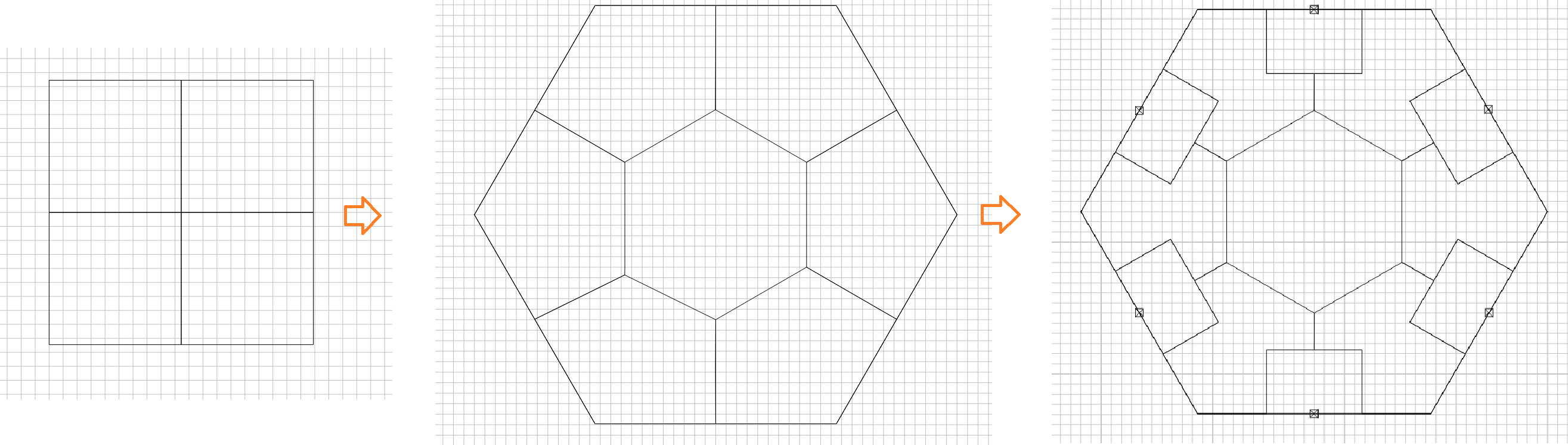
Design Evolution
When I simulated cutting this though I was getting remnant post material due to the cutter shape (being a newbie this was a surprise to me but pretty logical once I saw it). I wasn’t sure how to resolve it but due to the offset nature of the design I managed it by extending the design polygons to make the cutter extend past the corners. I’m not sure if this is ham fisted or the general path people use for achieving this - but it worked.
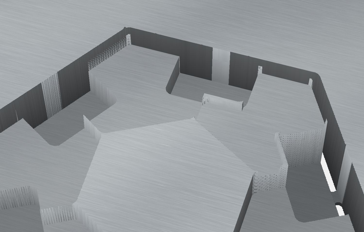
Remnant Post material
Extending the design polygons to ensure all remnants are cut
It was around this point I did my first test cut. I wont go into details yet but due to some issues I made my final design change which was to round off the outside edges of the wedge polygons. It created a smoother profile when cutting the perimeter also it looks better I think.
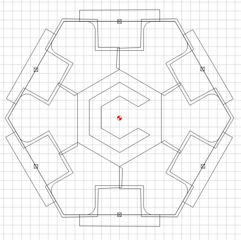
Final Design
CUTTING
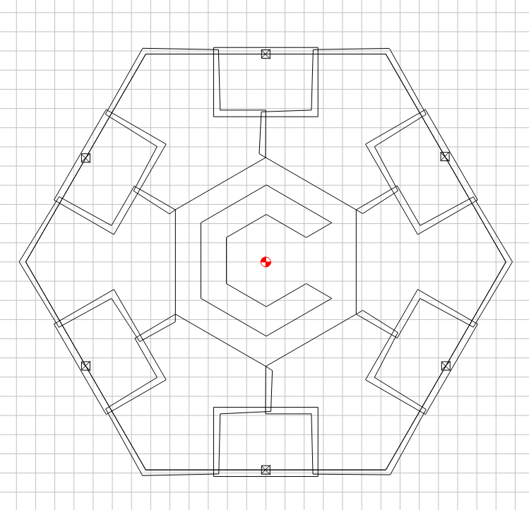
I used Carbide Motion. Generating the toolpaths was fun - particularly given all the changes in height for each poly. I just drew myself up a little height map though and followed it around and it all went well.
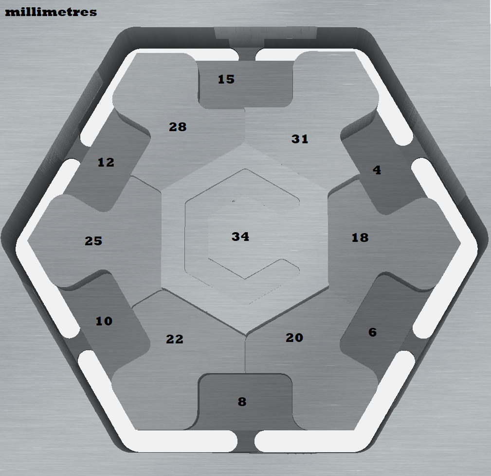
Height Map
Material - I used was two sheets of 17mm form ply glued together to give a total height of the original work piece of around 34.6mm.
Cutter - Carbide 3D 201 - 0.25" Flat Cutter for all except the C text which I used a 102 0.125" flat cutter
Router - Makita. Set to around 2-ish on speed settings. My Tachometer wasn’t working very well but I think I was around 10500rpm.
Depth per pass - 2.35mm
Stepover - 2.86mm
Spindle Speed - ~10500rpm
Feed rate - 1200mm (I dropped it to 1505 from the recommended setting and then decreased it by 20% during the cutting).
Plunge rate 317mm
My initial test I used the default setting of Softwood in Carbide Create. To my uneducated eye it looked too aggressive. I was getting a lot of good clean cuts, but at times a lot of splintering and tear out. On this basis, for the second piece I changed the settings to Hardwood in Carbide Create and still manually decreased the Feed by about 400mm and increased the Spindle Speed.
The cut went pretty well. I did lose Z steps in my test cut - but this was a belt tension issue… I then lost a couple of Z steps in cut two also and i’m not quite sure why. I was at the glued interface of the two ply sheets which is a harder laminate type material - there was minor buildup of “stuff” at that point but I don’t know if that would be enough to cause lost steps. I restarted the job (I would love to know how to restart a job from a chosen line number?) and it all went well - go figure.
One issue was I went too conservative on my material thickness as I didn’t want to cut into my wasteboard…which is what it’s for, but its still so fresh and clean and I didn’t want to defile it. My calipers were saying the material was anywhere from 34.5 to 34.65 mm so I set the material height at 34.3mm. In the end this left quite a bit of material for me to jigsaw to break the piece out. In hindsight I should have quickly generated a new toolpath for the outside cut only - and made it 0.3mm deeper and re-ran it, chalk it up to another lesson learnt.
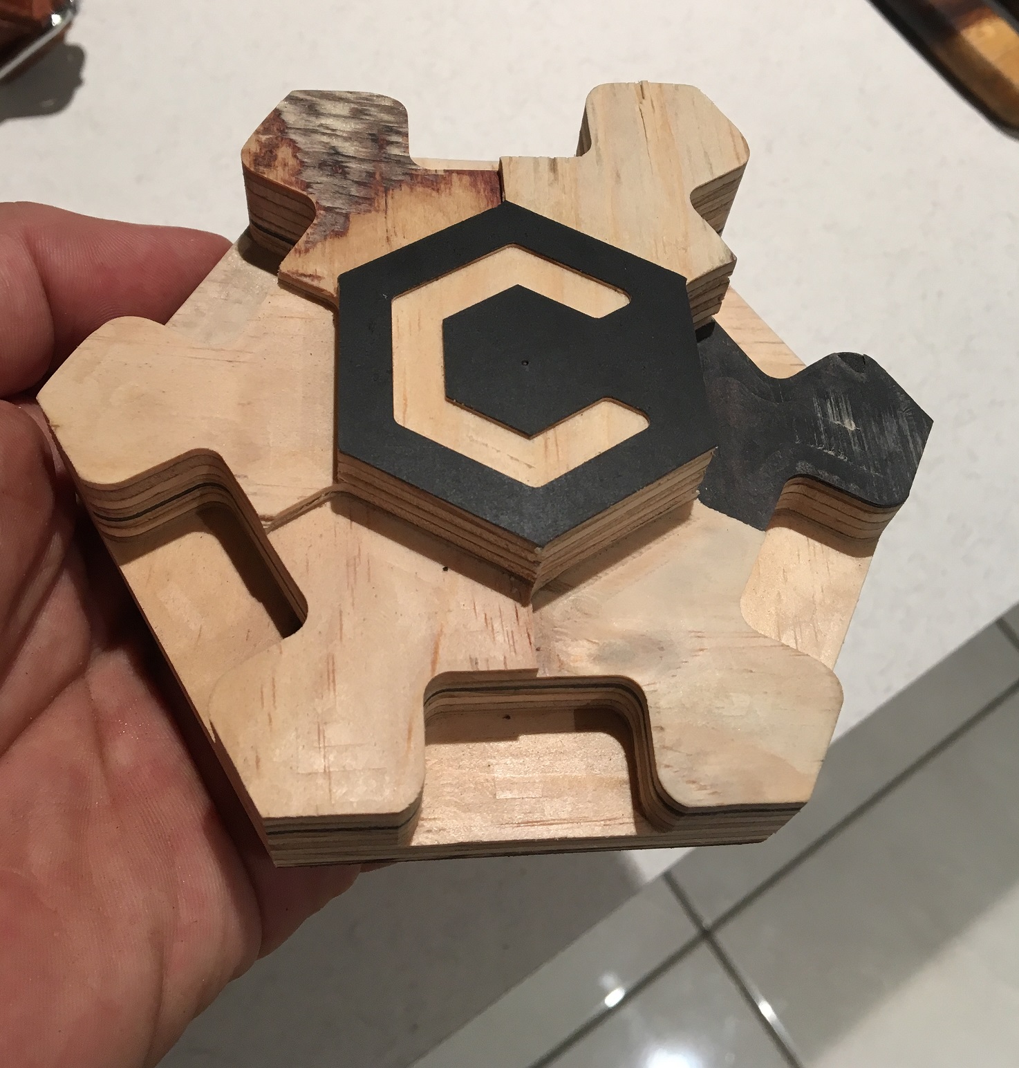
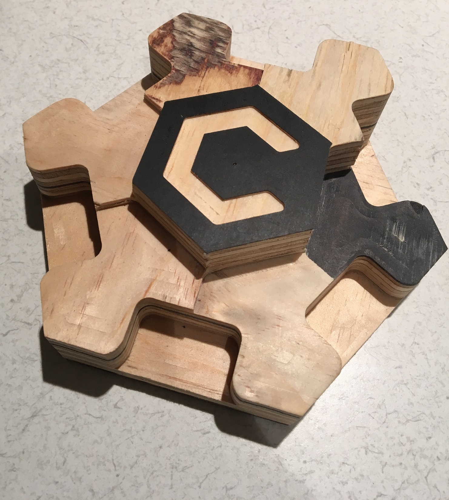
Finished Product
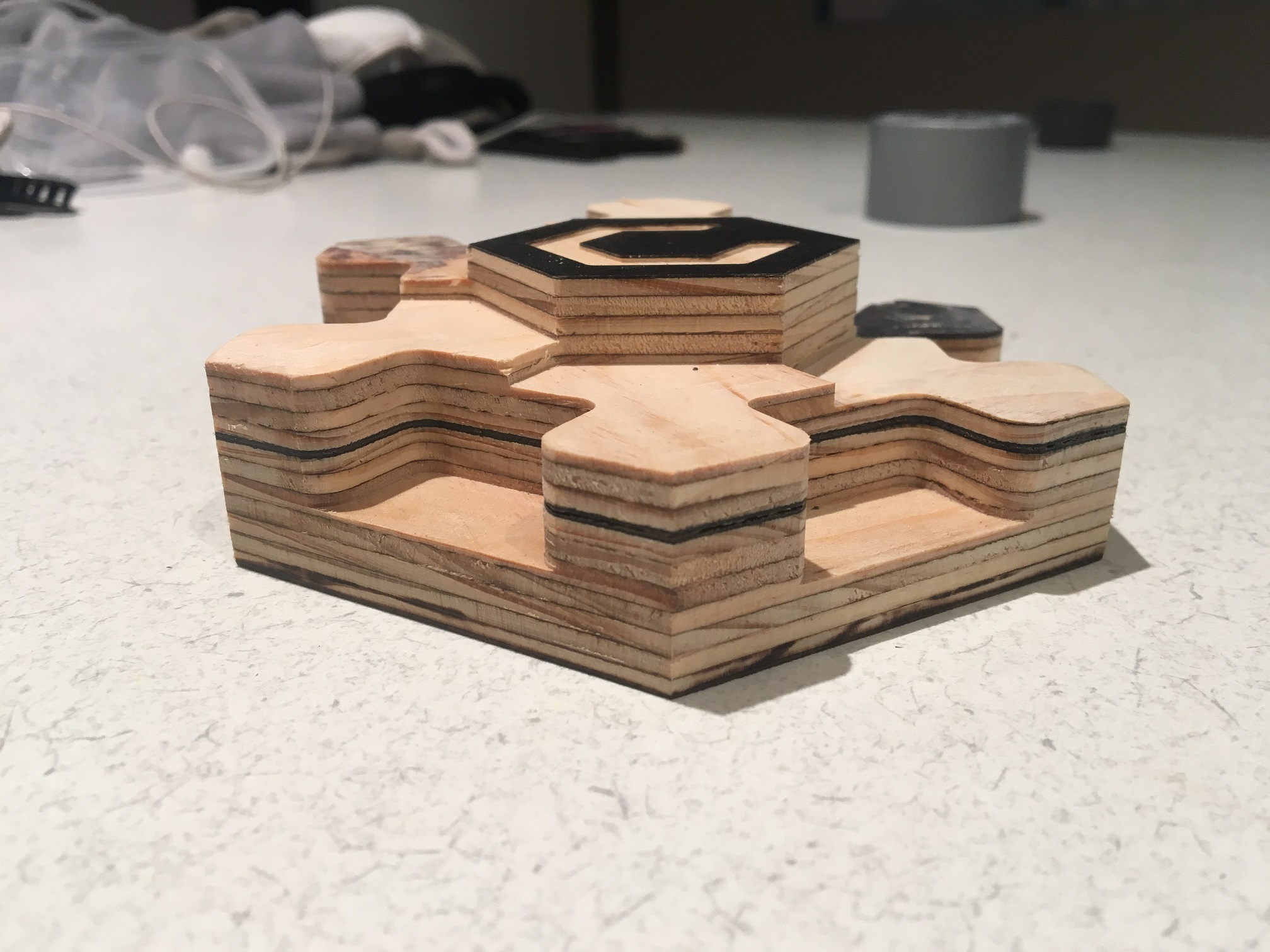
Side On
GENERAL - I’m really stoked with the outcome. I need to make three more now and then i’ll be set. I did see some limitations once I had it in my hands though…
1- it’s not practical for smaller tables or for work pieces that take up most of the XL and XXL workspace.
2 - if you have the T-Track work surface it won’t fit between outside rail and the Y axis. And you can’t have anything extending under the Y axis - another lesson learnt… I do have another design planned to address this though.
3 - the height variations are all between 2-3mm. Realistically do you need them that close? No, but I like the design so that’s ok.
Think that’s all for now, thanks for reading if you made it this far. If you’d like a copy of the files just message me with your email and i’ll pass them on.
Travis