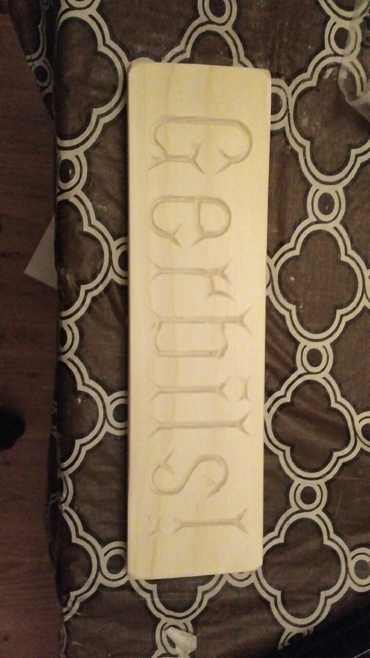
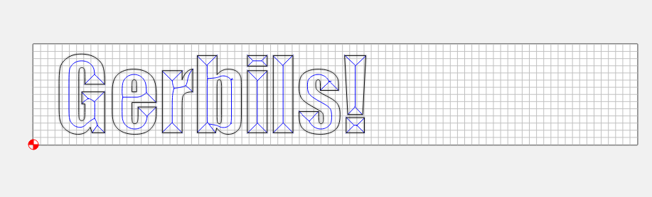
I was designing a simple sign, using the Impact font, using a v-carve toolpath.
When I look at it in the design or in the simulation, it looks exactly as I’d expect. When I save the gcode and actually run it in Carbide Motion, it produces the word I expect - but in a completely different font. I don’t understand how this could happen.
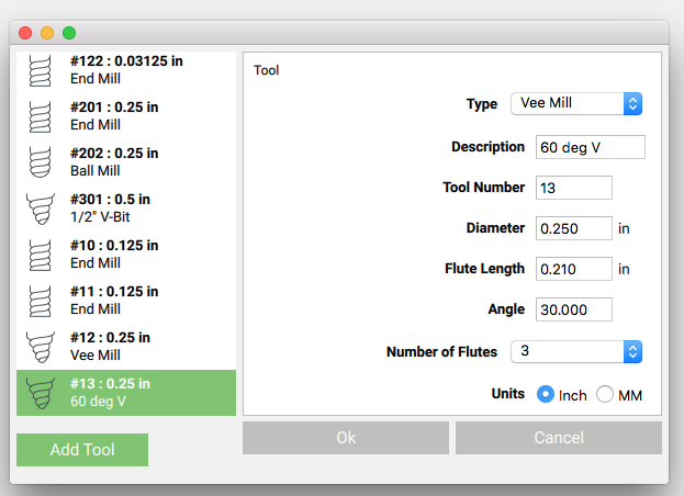
Looks like you got the taper angle wrong for the endmill — you’re using a much pointier endmill, which hence, is not removing as much material — for Carbide Create.
I believe the actual tool size is not the same as what the tool is in CC. CC thinks you are using a smaller or different angle bit. If you are using a 90 deg V set it to 45 deg, a 60 deg to 30 deg…ect
Yeah, it does exemplify different aspects of how letterforms were developed.
Folks who are curious about this sort of thing should read Fra. Catich’s work on the Roman letterforms and the origin of the serif, and Jan Tschichold’s books on alphabets, and F.W. Goudy’s book on the alphabet, and Warren Chappell’s The Living Alphabet, and Albert Kapr’s The ABC Book, and Oscar Ogg’s The 26 Letters (which was one of the first books I can remember reading).
Aha. It IS the same font, you are right - it just didn’t cut deep enough. That makes a lot of sense.
I think the angle was correct - it is supposed to be 60 degrees and that’s what I have set - but I think the flute length is wrong. I guess I’ll get out the micrometer and measure it and see if it behaves better if that is all right.
Yes, you have to define it as a 30 degree angle and the width at the top of the cutting part has to be at least as wide as the strokes of the letters being cut.
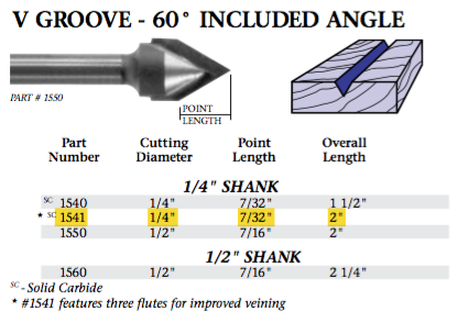
I’m looking at the first pictures again and see that the width of the letter strokes (assuming the grid squares are .25") are just under .75" wide. Looking at the bit that was used it appears to be perhaps only .5 wide at the top of the V so it wouldn’t be wide enough for that job. Also thinking that if the bit angle was entered as 60 degrees then the software would be calculating for a bit that was 120 degrees.