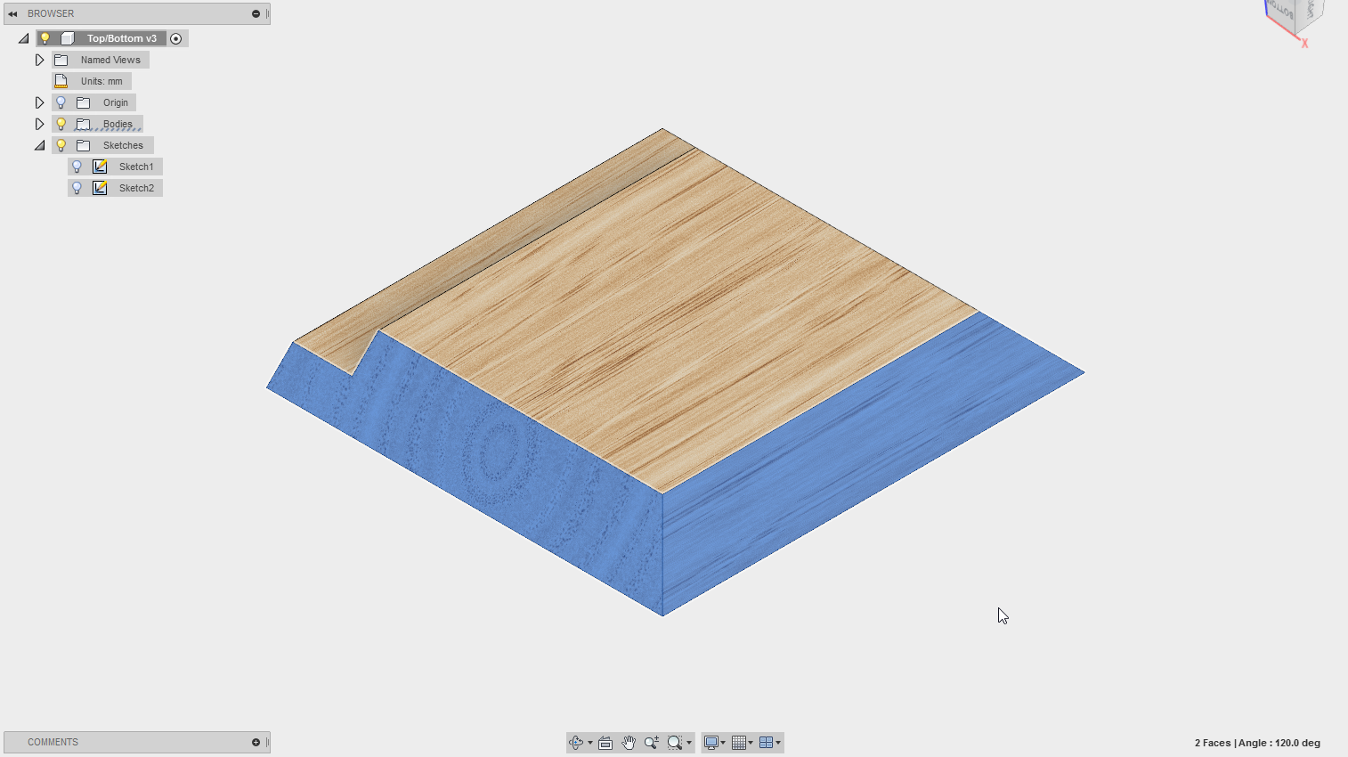
So I would like to try and machine the mitres on this part with my Shapeoko. My plan was to rough out the area around each joint and then use a large V bit to finish the mitres and get a perfect 45 degree joint.
I’m not entirely sure how to go about this… I would greatly appreciate any advice on this!!
This sort of thing is a good example of why I find myself drawing up and hand-coding stuff so as to get paths to match a drawing — I’m actually working up a hybrid technique where one has a single driver file and one gets a matching STL and SVG each of which can have CAM set up in an appropriate tool and “just work”.
For your part, there would be a 3D STL describing it, then an SVG which would be a square for the finishing pass and an inset rectangle for the rebate.
My suggestion would be to export a DXF and just do the V-bit finishing pass in Carbide Create. (Remember to set the stock origin from the bottom and be sure to have a surfaced wasteboard or fixture)
the main problem I have is that the chamfer is full depth in 20mm material and the vbits max doc is only 6.35mm so going need to figure out a way to do multiple passes, offset to accommodate the slope!
This is pretty easy to do, as is the same in Inventor/HSM.
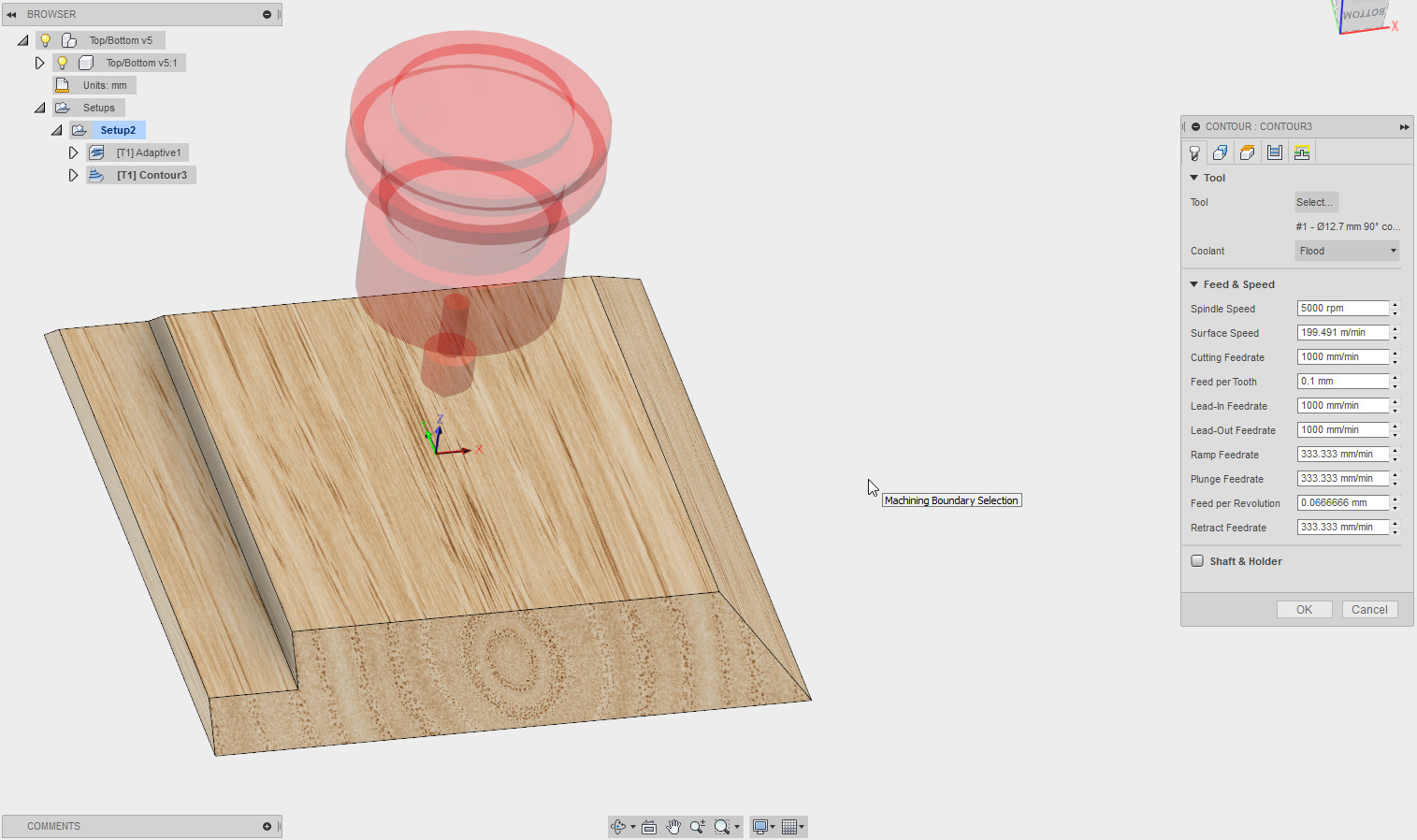
Rough it out (3-d adaptive is good for this) with an appropriate stock-to-leave for the final cut finishing cut.
The slope: The tool needs to be selected as a 45 degree chamfer bit with geometry defined to match your bit. Use care setting up the tool geometry, as if it is incorrect, the result will be less than good. It is possible a sample tool will match, but I doubt it. Use 3-d contour and select the bottom edge as your machining boundary. You can work with the stepdowns as needed, but if the proper tool geometry is set, it should be automatic.
If you are having difficulty in getting the tool Exactly where you want, be sure your top height is set to MODEL top, and then offset by -0.0001 or so. not enough to make a difference, but enough to get the path generation to only look at the slopes, or it will use the stock height. Also set the machining boundary to your model boundary. The flat depression at the rear of your model might require you to do this in two operations, one top to the flat area, the other the flat area to the bottom. You can do this by copying the operation and adjusting the top and bottom heights. That little tiny offset does the deal for you.
I would suggest posting this over in the Fusion360 forums. They are excellent over there about answering questions in a timely manner. They will take your design and even send you back one with it set up to do what you’re asking.
It is nothing in particular, other than to show the properties for the contour operation with the chamfer bit. Stock Fusion tools with no effort unspared on feeds and speeds. To see the operation details, you will need to bring it into fusion, as the web-browser interface doesn’t seem to let you see them.
The initial adaptive leaves 0.5mm for the final cleanup.
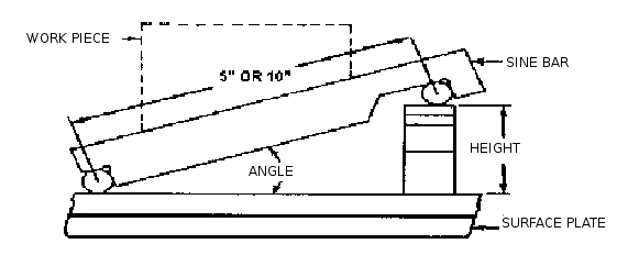
Another option that you can consider is fixturing the workpiece at a 45 degree angle using a sine bar and cutting in the x-y plane using a flat end mill. I’ve done this in the past to get precise angles on small pieces but you may have trouble with the size of your workpiece and the z-axis retract height limitations. Back of the envelope calculation shows that this would work if your workpiece is 4" square or smaller. It would also require 3 setups, but if all else fails…
I would suggest lying to your machine. Draw your pattern as if it had 1/8" X 1/8" steps on three sides, and tell your Create3d software you are using a 1/4" Flat End Mill, but when you cut, use the 45 degree V bit. The 45 degree cuts should all be tangent, if you have rectangular 1/4" contour patterns at 1/4" depth increments. It will take some simple addition and subraction to get the desired product size.