I’m creating some basic bits in Fusion 360, however the current item I want to make is double sided. Does anyone know how to pause the current process, flip the stock, then continue the process on the same design to add the tool paths?
The only way I can think to do this at the moment is creating a new design then run it as a separate operation.
Just create another setup to mill the other side but setting the zero to the adequate zero position on the other side. If you had setup the zero at the bottom left corner, do the same on the other side. It’s all about setting the zero adequately after the flip and keeping things aligned.
I just did a project just like this recently. Like Patricio suggested, you have to create multiple setups. For the top side, create your setup for your topside toolpaths and put those under it. Next, use your rotation tool and look at the bottom side of your project. Create a new setup (with stock settings and your WCS (Work Coordinate System)…which I suggest you use). Put all your bottom cut toolpaths under this new setup.
Here is a link to my project so you can see what I did:
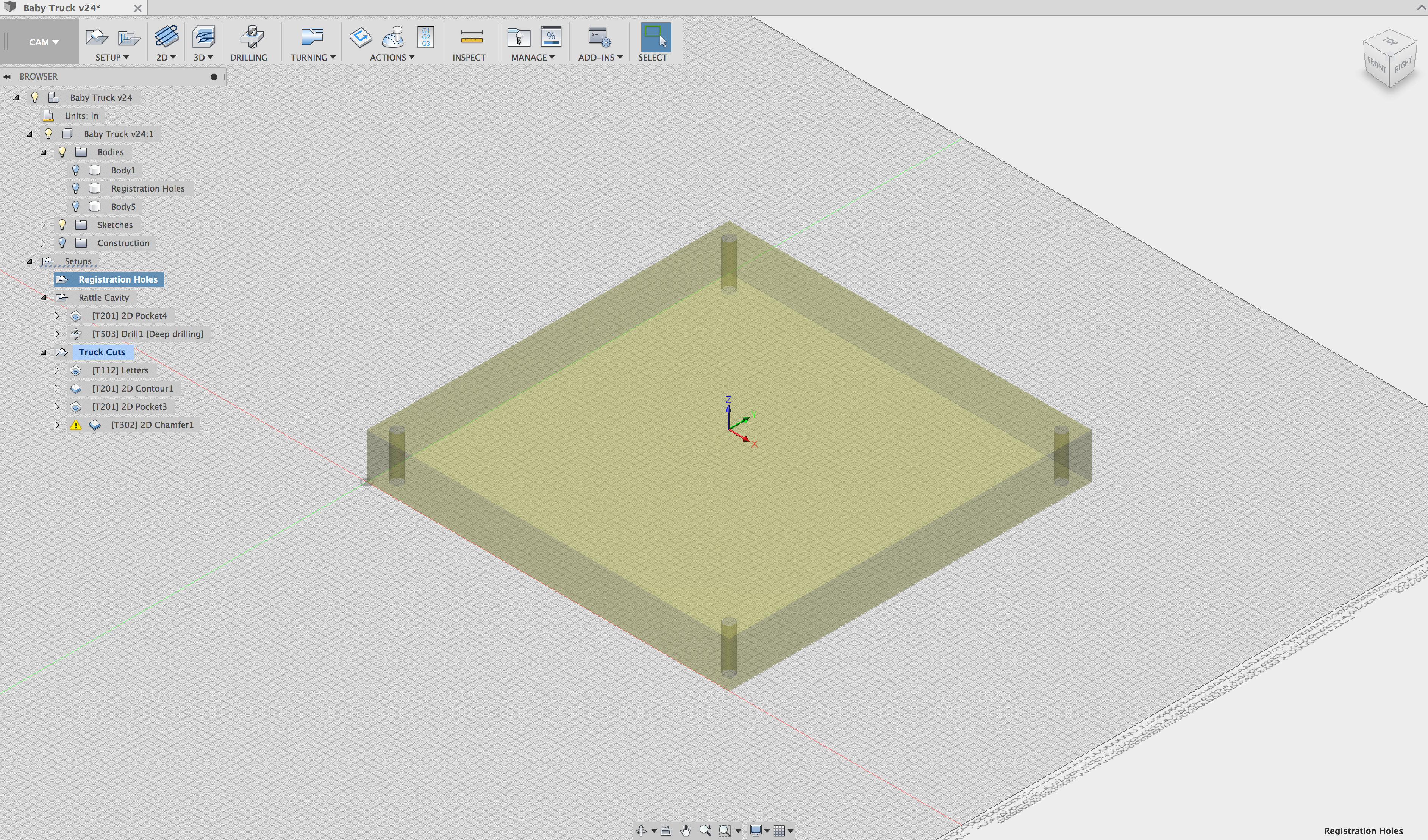
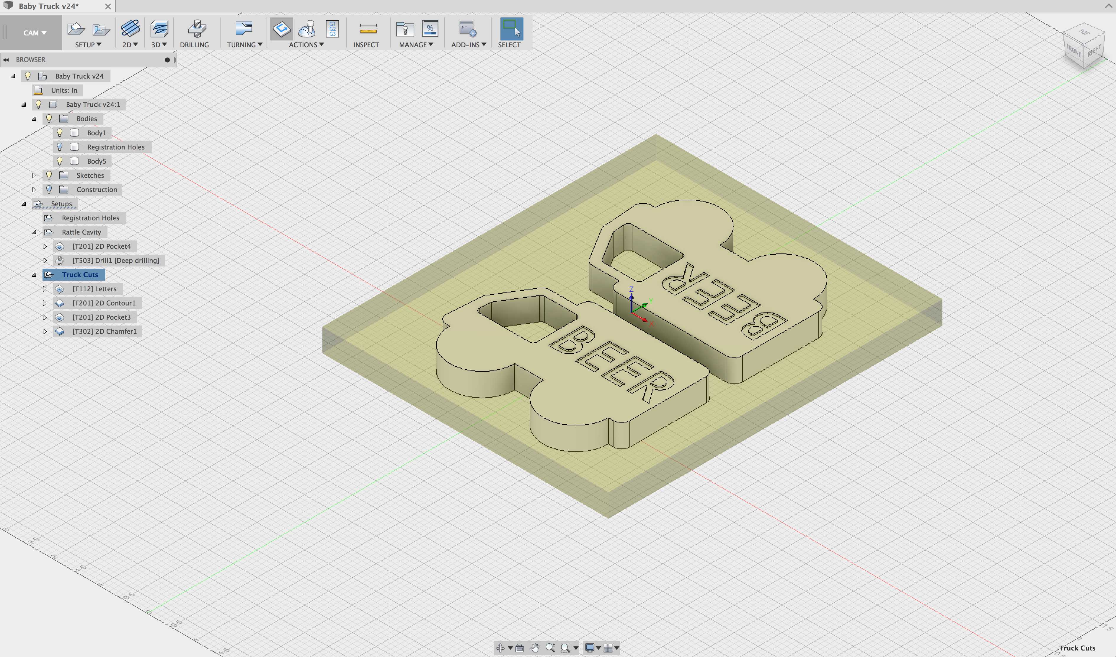
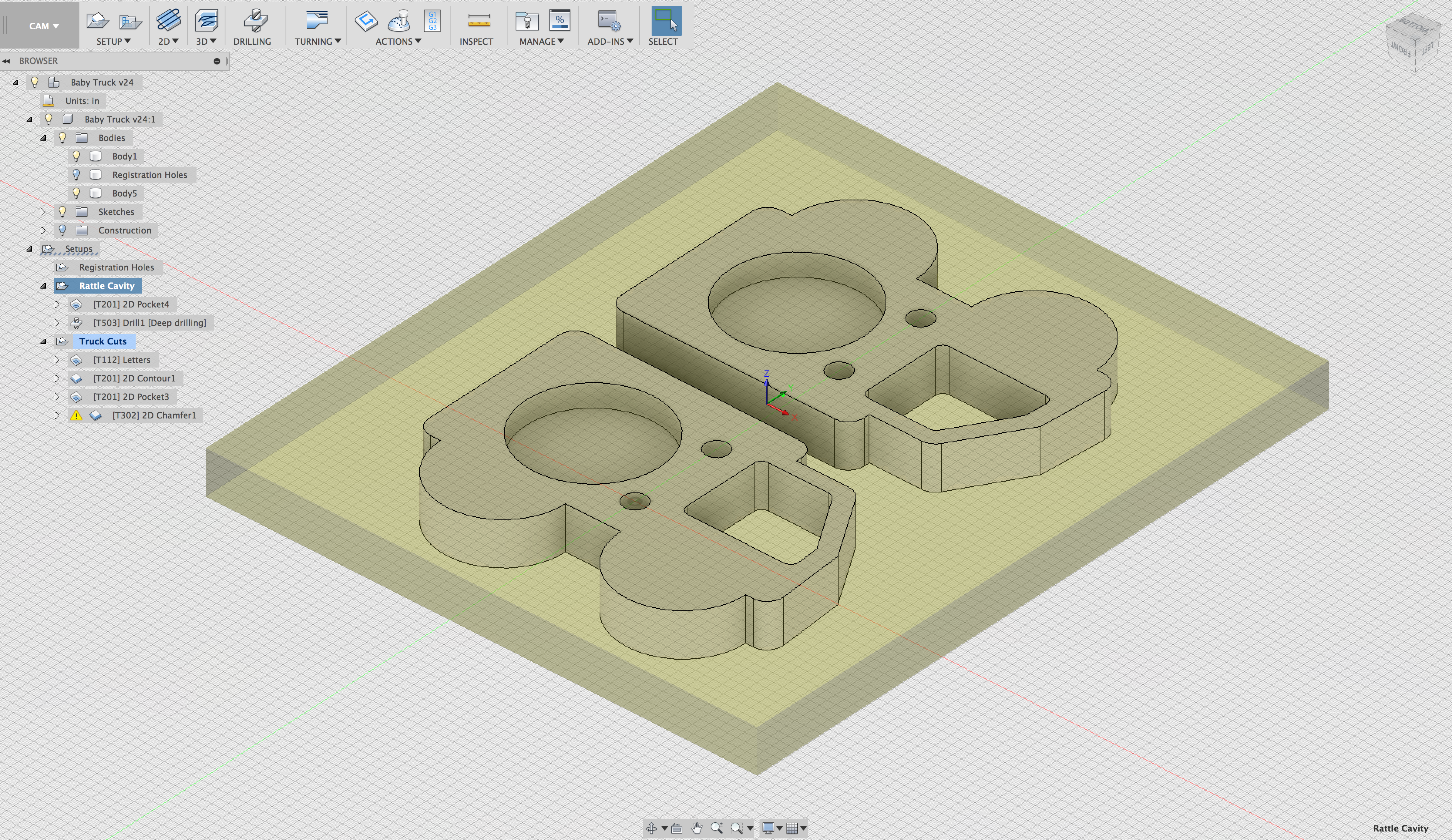
Also, a quick tip. I have a sea of holes milling bed. I use the center of the bed as my WCS zero and drill four holes on my stock that align to holes in the bed at equal distance from the center. This allows me to flip the stock just like the flip jig. This was my setup for a little rattle toy I made for my cousin who just had a baby boy. Him and his wife also just opened a brewery.
I was planning on running the complete file out on Carbide motion. When running the program with 2 setups will it pause between setups and ask you to continue similar to a tool change when using carbide create (my first time using 360).
@patofoto I like your idea. Did you also drill your table o secure it? However on my project I’m using small stock with minimal waste as its black walnut. I was planning on sticking it down with double sided and marking the edges with masking tape as opposed to clamping it/using a jig. I did this on MDF and had fairly consistent results.
Can I be cheeky and ask for someone to give it the once over before I run it on some test stock. This will be my first 360 attempt and to keep things easy I’m using the same 4 flute bit for the whole project.
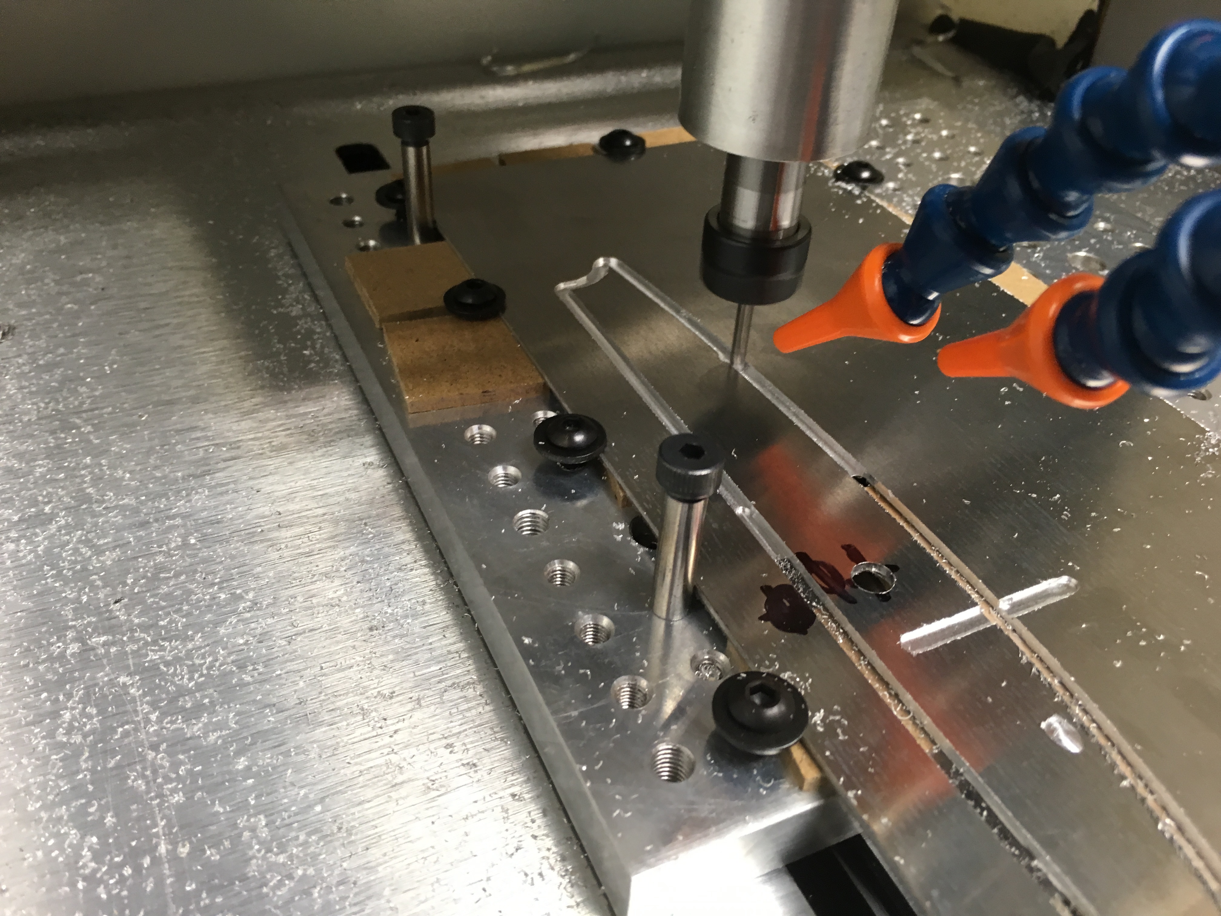
It all about how accurately you can place your piece after turning it and on your WCS zero. I think you have it at the bottom left corner of your stock and at milling table z depth. It looks like your stock is the same size of your piece, right?. You will only drill and mill holes, chamfer corners and mill a slot. I have stopped using tape. I don’t like the mess. I would use wedges to hold the piece in place with a corner milled into a wasteboard for registration. Like this:
Don’t pay attention to all the holes in the wasteboard. These were done as an experiment to using pegs for alignment. They worked but I dint’t like that the wasteboard material is too soft and would give with pressure. The idea is just to make a pocket that fits your part and some wedges to holt it. Holding material to the work table is unique to every part and project. It’s something that I’m still learning and experimenting with. If this piece you are making is just a one time deal, then maybe taping it might be a better solution for you. If you plan to make more than one, then maybe the slot and wedge would be more effective.
My table is all drilled with 10-32 holes at 1/2" spacings. Here is a link of another little experiment I did to test flipping using just the vise and careful zeroing and job setup. You can see my table there.
I would agree…the key is making sure you have an accurate flip. Make sure your X and Y zero are identical (Using WCS is key for this) and making sure your stock is in the exact spots when you flip it. I use a similar method to yours @patofoto except I’m using cams instead of wedges.
@UncommonDad Yeah, I have cams too that I made but find that they don’t hold tension too well. Mainly because I was using them with 1/4" pegs onto sea of holes drilled MDF spoil board. I would like to experiment with a more solid spoil board. How do you use your cams?. This is what I made:
I’ve used shoulder screws in a sea-of-holes bed for the nomad, works pretty well too. You need a known straight edge though. (this particular example is for a 180 degree rotate, but the same thing works for a flip)
@patofoto - I didn’t actually setup and stock infusion 360, I just setup the part I wanted to make - should I add this?
The clamp/wedge solutions look great, but not sure how I would implement on this design - It’s not just cut outs/holes but I’m trimming a few MM off each side and rounding corners. On my previous mill I use double sided car foam adhesive - it has very good holding properties and can be removed quite easily - However this won’t be suitable for all projects. I will need to drill my waste board or create something like you have above in some thicker MDF… I also want to make a clamp mount so I can use this on projects I am tempted to make a thicker waste board anyway - stock seems a bit thin?
I had a project that I had to mill out holes for medallions on some plaques and I needed a holding solution for the plaques. Holding wax and hot glue marred the finish, so I saw the cams somewhere else. I don’t have a fancy wasteboard solution, just a piece of scrap particle board. So I cut out some circles with an offset hole and screwed the cams down tight to the particle wasteboard. I put some duck tape around the edges of the cams to protect the finish on the plaques. They held real well I think because the screws held them in place tight.