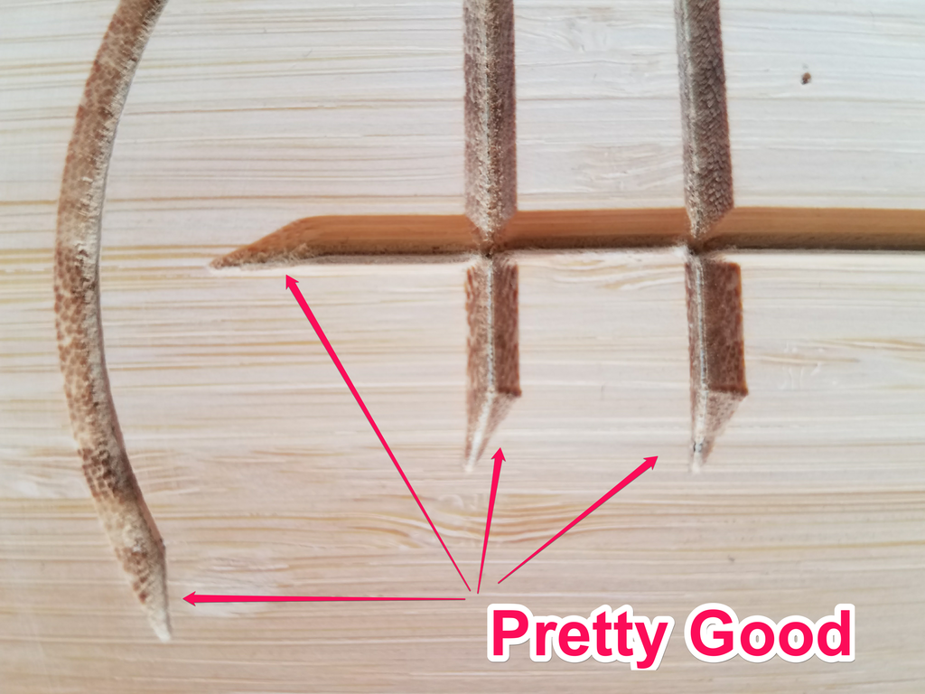
First test on bamboo was pretty good. I imported the line drawing into 360 as a dxf.
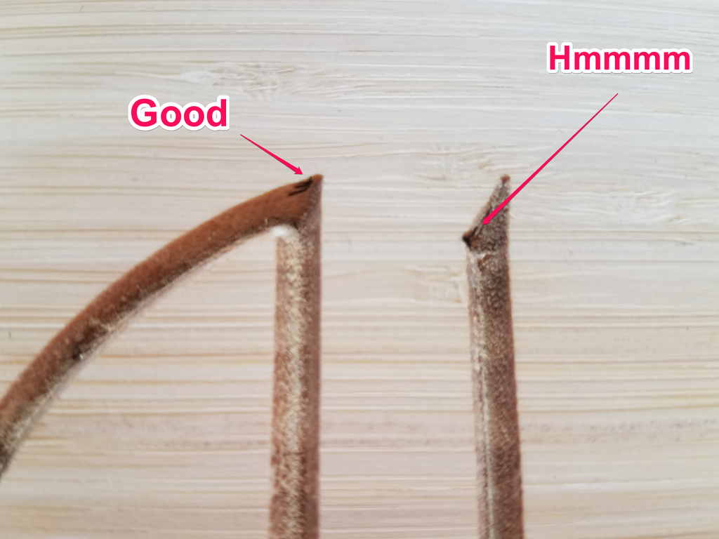
Only one corner had a little bulge where the vee bit did not quite get the corner correct.
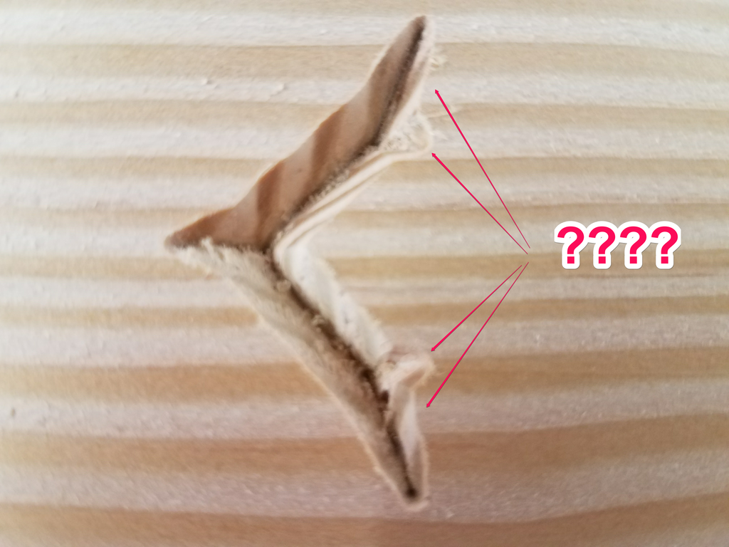
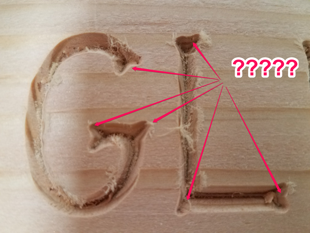
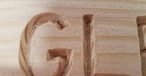
Next test in Douglas Fir was not so good. All the corners look like crap. Here I created everything in 360 and used a True Type Font for the outline. Using a square end mill and 3d pocket clearing the font comes out perfect. Using the engraving option and a vee bit (same tool setup as before) and it looks terrible.
I know the bamboo cuts better than the Fir, But I don’t think the wood alone can account for the difference in quality.
Does this look like a problem anyone else has had?
I’ve seen this exact thing, and this is a Z-height issue - the zero is set too low. Carefully set z-zero using a known thickness shim between the tip of the v-bit and the surface of the material so the tip doesn’t dig into the material. I use a .125" piece of brass (that’s actually .123" in my case)
Actually it was the chamfer angle. Fusion 360 was configured for 45 degrees and the tool was 30 degrees (or 60 degrees, depending on your point of view).
I ran it through the planer and ran the job again and the corners were fine.
I thought the letters could have been heavier so I dropped the tool 2mm and ran again. So the corners are a bit rounded from the tool being low, but I like the letter weight.