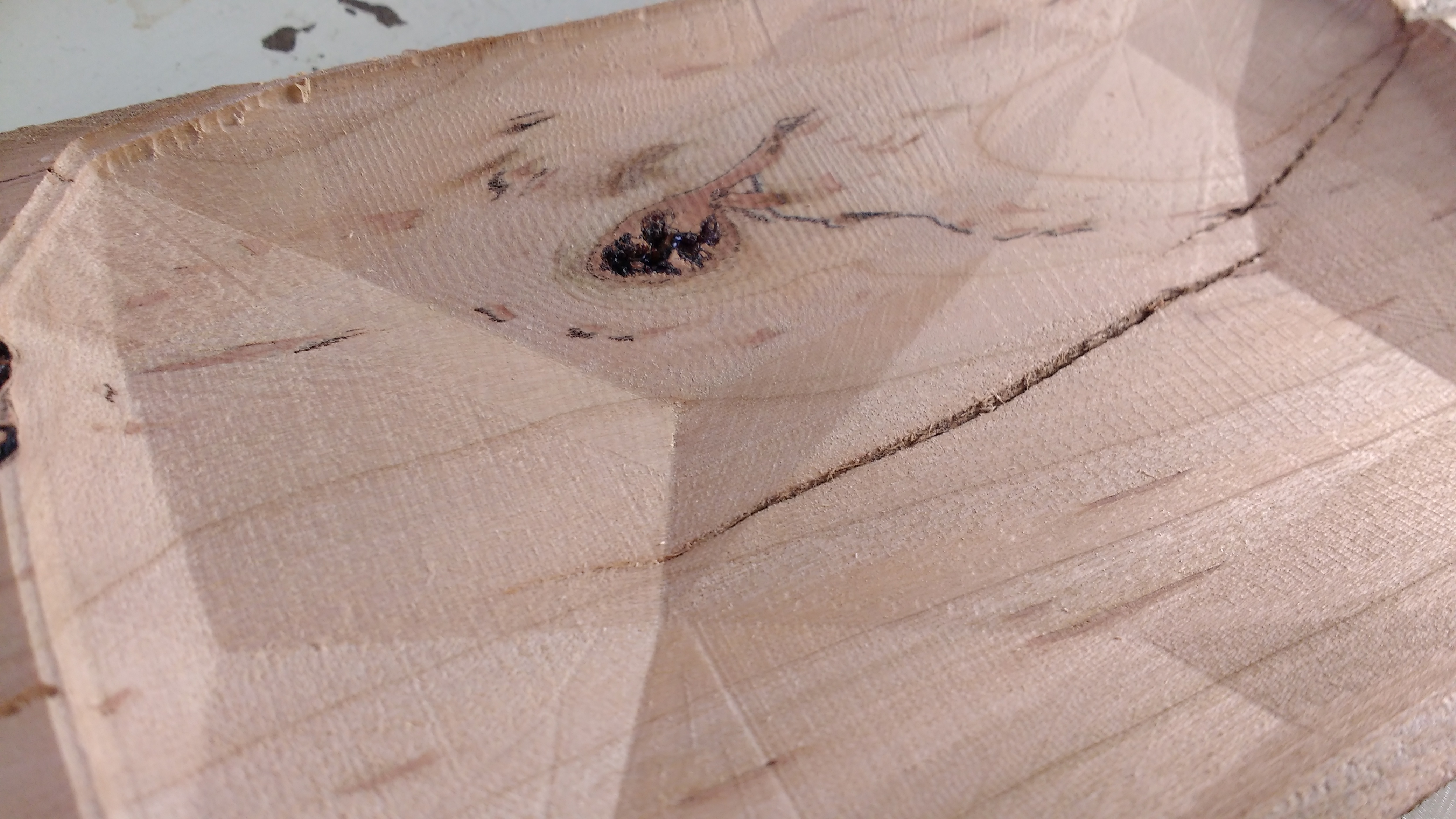
I’m carving a dish design on my S3, but I’m having trouble with smoothness of the cut. Since this is a geometric concave design, it’s not really something I can easily sand. Is it some kind of tool chatter? Is it a problem with my bit? Do I need to tighten/loosen something?
This is carved in a cherry wood scrap, but pine and poplar have all had similar results. I’m using a #101 bit (.125 ball cutter), but it’s roughed out beforehand. My software is a little unconventional for this group, but I use VCarve Pro to generate gcode, and CncJS to communicate with the machine.
Is it chatter or just lines left from step over with a round nose cutter? Hard to tell from the picture what scale the piece is, but could you use a 1/4" ball nose cutter and small step over, like say 10%? What % step over are you using with the 1/8" cutter?
I’m not really sure what is causing it. I don’t think it’s stepover, because the grooves are parallel to the path. They seem to be at a regular pattern, so now I’m thinking it’s not really chatter, but something I haven’t tuned properly? Could enclosure wobble contribute to it too?
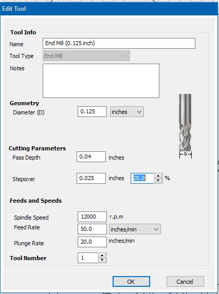
I’m using 10% stepover, so I’d think on a .125" cutter that would be decent? The entire piece is around 3x5; in the picture, that main triangle facet with the knot on it about 3" wide.
Just hoping someone’s seen this same issue and solved it already
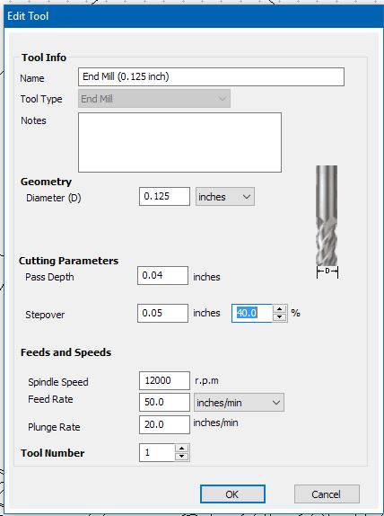
Are you sure that’s not reversed? In VCarve at least the percentage is based on the tool width, so the lower the percentage, the smaller the stepover width. Disclaimer: May be different in different software:
Different apps seem to do it differently, which is why I suggested drawing it up, then making a test cut and comparing — I just always use 50% — it’s unambiguous and usually good enough for my purposes.
I made a smaller model and tried eleven different variations of speed, stepover, and toolpath strategy. What I’m seeing is that slowing down the carving helps the most, so I guess I need to go and recheck my belts and wheels again?
Also, choosing a toolpath strategy that travels mostly along the grain helps hide a lot of defects, as expected The default in VCarve is “Offset” (similar to waterline in MeshCAM, I think), which means every angle the light hits, you’ll see some cuts.
Stepover is as Dan mentioned for me, since we’re using VCarve. I need to play with that to find a good balance of speed and sharpness.
Luke, I haven’t noticed that (and does it matter too much with a roundover?), but it also made me rethink my clamping strategy. Will try some other options and see if that makes a difference.
Hey Jarrett - slowing things down usually helps - there is less chance you drag the cutter - instead all the tiny blades make tiny little cuts in whatever your cutting - wood is very fibrous over say PVC. Put a pineapple in a juicer and you will see what I mean
The reason I mention the sound of the cutter is if the mill bit is at an angle it places more friction on one side and only uses part of the cutter - again imagine you have a round bar at an angle and you drag it in some sand. The profile the bar would leave is that of a U - however if it was dragged vertically it would have a flat profile. If the bit is at an angle/i.e. your mill isn’t straight it will be cutting at a U which increases friction on one part of the mill, and also leaves a rougher pass as the whole bit is not making contact. That friction usually changes the sound of the mill - this is something I learnt over time and many f**k up later…
Another consideration here is one we were discussing somewhere else — the relative length of the cutting surface to the chip removed, and the shape of the chip and the ease w/ which the machine can start the cut — I believe ball-nosed endmills are at a disadvantage relative to other shapes, and belike the feed rates need to be adjusted to take that into account.
I have stated using a clearing strategy - using a 1/4 flat mill leaving approx 0.4mm. Then running a passing pass over with a finishing mill such as a round bit.
I did do a whole aluminium model with a round end bit - took ages…