Help me be part of the so3 family :)

Hi guys, so a little bit about me and my project to place some context in order for you to understand my needs and advice me the best.

I am a podiatrist in Belgium, and I wanted to start a cad/cam for my insoles (around mid-end 2019). I’ve already go through some of the kits big podiatry company were selling and it’s rather expensive and not at my taste(huge boxes encasing small surface areas, with lost of space) , even tho if they do sell it I suppose it is working decently enough.
But I m sure I can get something that will do the job nicely, be more affordable and fit my needs better elsewhere in the Cnc world. The fact that only the Z axis is moving on their cnc is bothering me tbh (moving x/y table)

So i started to read and document myself about the Cnc world, I ve been trough the “cad cam education” app and it was very interesting and well explained. In this app I learned about: cnc mechanical overview, end mills and cuttings, CAD, CAM how motion was created, g code, practical tips and more, let’s say the basics to enter this world I guess?

Now that I know a bit more about it (correct me if I m wrong), what I will need to make my idea into something I can work with is:

The footprint of my patients -> 3d scan
The 3d file should be compatible with the cad software : 3d scan- > compatible cad software
The software will give me a file from the insole that a cnc can read as G code - > file for toolpath
Or I need to use a cam software to define the toolpath for the cnc to read.
Then comes all the technical part about fitting my milling machine: depth of cuts, toolpaths, change of tools, speed and feed, etc.
Plus non related technical stuff about soles from there.

My needs:
For the software (3d scan and design) I ll visit the big resellers for podiatrist as the design part should be better than the regular cad from carbide3d for what I need to do.

For the hardware: depending if the software allow for multiple insole in the same time, I might need a bigger surface, otherwise something like the classic shapeoko should be enough. Or would you advice me to go bigger? (planning on using it for private use until the mid-end 2019deadline)
The heigh will be around 4-5cm at max so no issues there either.

The material that will be milled is ethyl vinyl acetate foam (Eva, hardness from 35 to 70 shore (mostly 70 (80%))
About the end mills : I ll need something for the big cuts, the precision cuts and a spare one at least. But I don’t know what kind of end mills is best for this material (spiral up cut or strait flute for the big pass? And something like a ball nose for the details? Plus one surfacing and one spare part) or what do you guys would recommand me?

Does anyone here have already worked with Eva? How is it respond considering speed and feed (if someone could give me a spreadsheet or smtgh that would be nice)

What I need from you: a review of my thinking about the cnc, good sources to read about what was (not) wrong in my writing, Intel about common files type in the cnc world, general advice about my situation and the option that would work the best for me :slight_smile:

Thanks fellas.

1 Like

Hi Géry.

Sounds like an interesting endeavour, and it looks to me like you are off to a good start, you have the basic concepts/workflow right.
Make sure the output of the 3D scan is a “standard” 3D format, e.g. STL.
Then pick a CAD/CAM software that can handle 3D (Fusion360, MeshCam, …). Carbide Create cannot (really) do 3D for example.
This software will indeed generate G-code for the Shapeoko, based on the STL model AND the many toolpaths settings you will have to tune (e.g. feeds & speed, depth of cut, etc…)
The size of the Shapeoko will depend on whether you intend to do “mass production” of these soles, i.e. you may want the ability to cut many of them in one go. Otherwise a standard Shapeoko should be just fine.
I never used EVA so I won’t comment.
I’m sure you’ll get plenty of excellent detailed advice from Shapeoko gurus around here, just wanted to say hi from France before most of the community wakes up and provides better answers :slight_smile:

Julien

1 Like

We’ve gotten a couple of sample files from other podiatrists looking into this sort of thing.

The scanning software seems to default to outputting just a plane/surface description, so you’ll need to marry that up with the stock size and the size of the insert which you wish to cut out. Once that’s done, CAM will be easy using a tool such as MeshCAM.

EVA foam cuts easily, and there are specialty endmills for cutting foam, which I’d suggest looking into, e.g., the

Amana Tool 46270 Solid Carbide Foam Cutting Up-Cut Spiral 1/8 D x 1-1/8 CH x 1/4 SHK x 2-1/2 Inch Long Flat Bottom Router Bit

You’ve got the right idea on the different tools, though some folks find it’s just faster to leave one ball-nosed endmill loaded and just cut with it, making up for the added time in the toolpaths by saving on the endmill changes. We have a bit on endmills at: Carbide 3D Tooling Guide - Carbide 3D

I believe with a fixture to hold standard sized blanks there wouldn’t be a need for a larger machine — cut a pair of inserts, then when they’re done cutting, load the next insert and post-process the ones just cut — where a larger machine might come into play is if the raw material is available in large sheets, then it might make sense to cut said sheets to fit the fixture and a larger machine might be better at that. Alternately, you could just feed in a sheet (say from the back) and cut out inserts as needed, then cut off the waste and advance the sheet — probably an XL would be the best compromise, assuming the stock material is narrow enough to fit through the machine (if the stock material would fit through an SO3, no need even for an XL).

For some information on file formats see: File formats - ShapeOko

Here is the updated link for the wiki…
https://wiki.shapeoko.com/index.php/File_formats

1 Like

Greetings Géry,

The footprint of my patients -> 3d scan
The 3d file should be compatible with the cad software : 3d scan- > compatible cad software

YES, 3D scanner output needs to be a standard format such as STL, OBJ, etc., that your CAD program can import. The output might need to be refined prior to importing. Your CAD program might import polygon files with triangular structure, or quads structure, or both. There might be a need to reduce the 3D Scan resolution, so that the file can be imported, and there is an opportunity to correct any mistakes or add detail to the 3D Scan form prior to importing into CAD. One might need a polygon modeling software to accomplish this task. There are several available at no cost or affordable prices.

CAD software provides digital tools to create the object geometry in a mathematically precise way.

CAM software is where one utilizes different cutting strategies to remove material. The output from CAM is the cutting directions, or tool paths.

This output file is what is read by the G-Code Sender to the CNC (it is like the driver of the automobile).

Then comes all the technical part about fitting my milling machine: depth of cuts, toolpaths, change of tools, speed and feed, etc.
Plus non related technical stuff about soles from there.

Hello all,

Ho damn already two weeks since i posted…
Time went so quickly! So i apologize to all for replying so late.

@Julien You were right! I indeed got plenty of advices :). I guess the 3dscan i ll have will be standard, at least i’ll choose one based on that (i don’t know wich one yet). Is the shape of an insole considered as 2.5D as the bottom is flat and could be like 2.5 axis or it will be a pure 3d design? (And hi neighbour!)

@WillAdams Hey i was curious to see what you tought about my project. From the post i read, you always bring nice ideas.
i tought too that i was not the first one to look into this. I’ll dig trough MeshCAM to know more about.
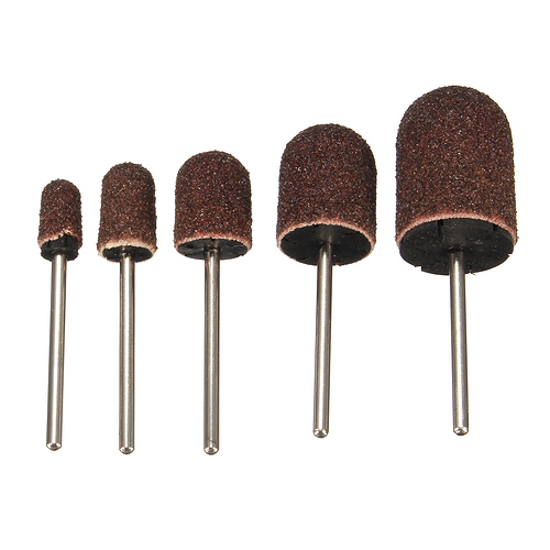
I’ve checked about the tools file and the ref you gave me, based on what i’ve seen in build-in packs from podiatry they tend to use real thick ones or something looking like that (couldn’t find a pic, might do one from the mill of a co-worker if needed) :

Bits commonly used from what i've seen

So is the one you suggested a one for all kind of bit (i mean could i got precise curves and smooth bottom with a flat end bit and using only one tool? or should more passes/bits be needed?) Or only a ball-nosed could do that? How will the shank affect the cutting precision (for a ball-nosed / flat bottom?) Upcut seems the way to go for EVA.
I could go for only one tool as it would be more convenient, but the toolpath should therefore do another pass to avoid the ‘waves’ into to material, considering it’s a ball-nosed end mill, if i got it right. Still not sure if i would need a flat end ( flat bottom for the forefoot and the shape around the sole) or a ball-nosed (organic shapes with curves for the rearfoot and midfoot) that would need more passes on the forefoot to flatten it (avoid scallops).
Best option should be the most time effective-easy to set (or am i asking too much :stuck_out_tongue: ).
I like your idea about a rolled raw material, this might be possible and could be convenient.
Thanks for the links, it helped answer some question i had :slight_smile:

@Artistan Thank you to bring some up to date link.

@Tem Hi thanks to pass helping me with my project!
So about the 3d scan the more won’t always be the better then? Could you devellop about the correction prior to import? From the link William and Artistan gave me, STL is a mesh of triangles ( like in video games so?) so i would need something specific for this shape (triangle) or they are all polygon compatible (would make more sense imo)

Thanks to all, it helped a lot, it also bring me new questions to think about and stuff to read about, nice challenge, but i’ll have to keep my post living so it’s complete and could help others in the same situation.

I believe your best bet will be to find a ball-nosed endmill which is optimized for use with foam (# of flutes, flute shape) and just use that — you’ll want a ball-nosed endmill for the 3D shaping: http://docs.carbide3d.com/tutorials/tutorial-tooling/

My experience when importing a 3d scan mesh is that it needs some correction, either more definition in some regions of the 3d scan mesh or smoothing/filling to remove irregularities. The few 3D scanners I have used create triangle polygon meshes. There are some programs that recreate those mesh objects in quad polygons. The quad polygon meshes seem better suited for conversion to solids and surfaces in Fusion 360 and a few other CAD apps (SharkFX + Powerpack). The workflow might be as follows: Scan, export, import to refine mesh, change to quads, export, import into Fusion 360 to refine into mathematically precise surfaces/solid model part, use included CAM module to create tool paths, export g-code, import/open g-code into G-Code sender. Secure stock material to spoil board, zero machine, machine away unneeded material from stock to leave part. (this is simplified)

This topic was automatically closed 30 days after the last reply. New replies are no longer allowed.