Help staving off Insanity

I am in need of some help to stave off insanity.

I am attempting to reproduce the “Planet Clock” using the plans graciously shared by Gary Lamon @GaryL.

The few things that I’ve cut since I received my XXL have not required very close tolerances.

I have nobody but myself to blame for the results I’m getting because of my failure to calibrate my machine.

After cutting several of the pieces for the clock I first noticed that holes that should be 1" in diameter wouldn’t receive a 1" dowel. They were not only .97 in one direction, but .92 in the other.

Holes with a diameter of 5/16th that were cut as a Pocket with a 1/4" endmill were also smaller than needed and also out of round.

After several other measurements, I realized I might as well forget about cutting the remaining parts.

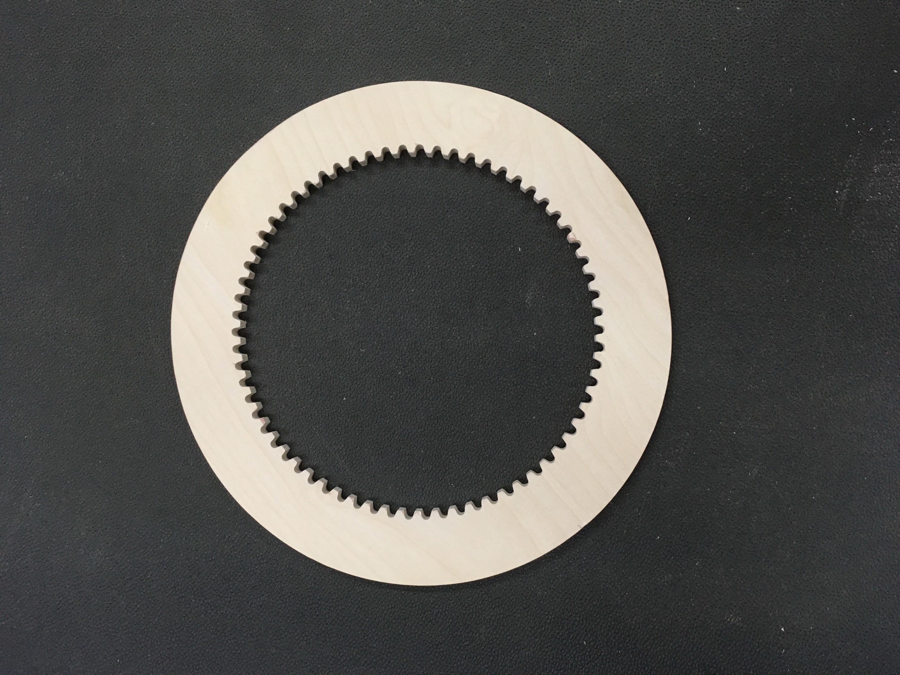
The following photo is of the Ring Gear and should be 15" in diameter. It measures X = 15.0625, Y = 15.25.

The following photo is of the Back Plate and should measure 15" across the X Axis. It actually measures 15.0615. The Y Axis should measure 23.8562. It measures 23.875.

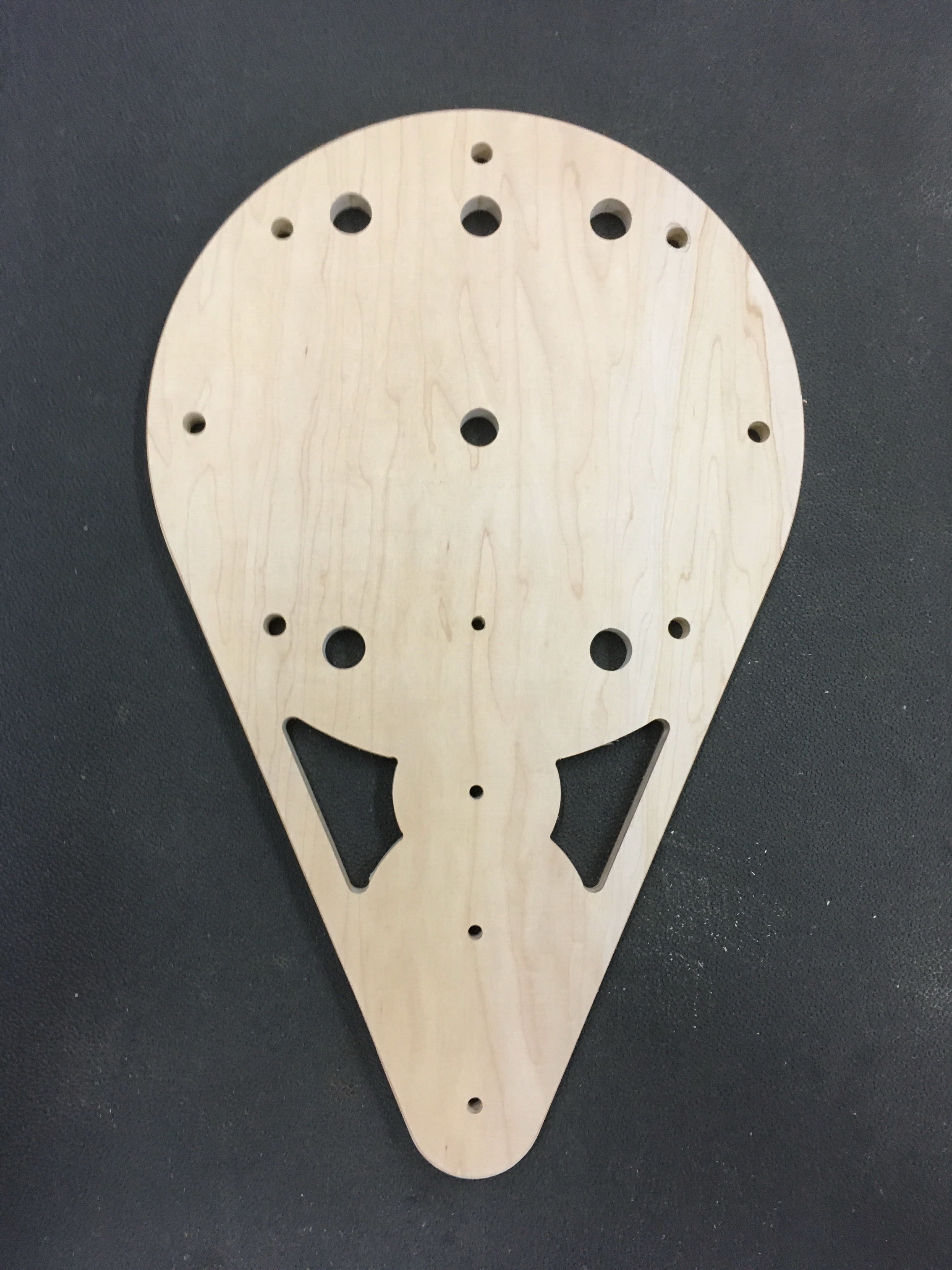
The following photo shows the relative position of the two pieces which will be separated by 1" dowels when assembled. In the X Axis, the both pieces measure 15.0625 +/- .005, about as close as can be expected.

The Y Axis of the Back Plate is off by only +.0188, but the Y Axis of the Ring Gear is off by over a quarter inch.

I’ve tried the “Three holes in a triangle” test. I’ve created the Test Pattern of my own pictured below. They both show irregularities and both small and large errors.

I’ve measured circle to circle Up, Down, Diagonal, and Diameter. I’ve measured the Square height, width and diagonal.

I have been reading post after post on calibration. I’ve read of those who tried the “Belt Stretch” formula for the $100 & $101 settings who get good results on paths of one size object but the same object again with a smaller size was off.

One post says that doing the calculations was not a good idea.

One post says the calculation was actually backwards. Expected divided by Measured should have been Measured divided by Expected.

I’ve tried the corrected formula and plugged in the results with no consistency.

Is there anyone out there who could say “Bill, here’s Step 1, Step 2… Follow these steps and you should get accurate and consistent results”? I’m not asking for perfection, just acceptable and mainly Consistent results.

I’m going nuts here.

Thanks for your anticipated comments.

1 Like

I am assuming you have checked your belts and V-Wheels for good tension etc.
The documentation I followed was here:

http://docs.carbide3d.com/article/42-how-to-calibrate-the-machine-for-belt-stretch

It worked well, the results were consistent for me. If it’s not consistent look into the hardware any make sure nothing is slipping and make sure the pulleys on the belt are tight and that they are tight on the motors also.
I also had to adjust the parameters a little bit to get good results. I can’t say I was out .25 inches but then again I didn’t try making anything as large as 15 inches while I was calibrating either so who knows!

3 Likes

One of the things I should have done before resetting the used machine I purchased to defaults would have been recording the changes they made to those settings, because the machine was very accurate before I got my fingers into it.

This thread and the article will come in very handy!

Here’s MY spreadsheet for doing this calibration, and it works fine for me. I did mine with a 2" square because thats the scale of stuff I need the precision for. I’ve checked against 10" items, and it’s close enough. They are belts. They don’t stretch in exactly the same way all along their length, so there will be -some- variance, but on average, it shouldn’t cause any major issues.

Before you start, check that your v-wheels are adjusted properly, and all the set screws are tight and in place on the flats of the shafts.

Remember, the value you are setting is the number of steps per unit of length. You would expect that if it cuts too short, the value is too small. If it cuts too long, the value is too big. In theory, you could do this over and over and adjust the value a little at a time (0.1?) and home in on it, but it would get really old really fast. You can do it in one pass with a little calculation.

I used HDPE for this because it was stable, and I was tired of messing with MDF. It doesn’t matter much what you use, something hard enough to be easy to repeatedly measure is good, but soft enough you can cut it in one pass is nice.

Bill, here’s step…

  1. Cut a square. I’ll leave that part to you. Something small enough to fit in your calipers. 2-4" is reasonable, bigger is better than smaller.
  2. Measure X (USE CALIPERS!!! Do not attempt to do this with a ruler.)
  3. Measure Y
  4. Using the spreadsheet, enter the X and Y values, the size of the square you intended to cut, and the $100, $101 values you CURRENTLY have set.
  5. The bottom of the sheet will show you what to set the values to. Set the values via the MDI screen in CM.
  6. Cut a square.
  7. Measure X (USE CALIPERS)
  8. Measure Y
  9. Close enough? No: Enter the values from step 5 in the top part of the spreadsheet for the “Current” settings, and go to step 4. Yes: Stop.

You can do this with Z, but you need to cut a stair step and that’s a little more involved. The spreadsheet process is the same.

You shouldn’t need to do this over and over to refine it. Belts do stretch over time, so you should expect to do this periodically, but it shouldn’t take more than cutting a square once and adjusting each time. I keep a label on my machine for the last time I did this so I don’t forget (shows date of calibration, and date of belt install)

Shapeoko3-Calibration.xlsx.zip (14.7 KB)

5 Likes

Am I missing something? Is there a spreadsheet out there I can use?

Thanks, Les

Doh!!! You’re not missing anything…I did… It’s over here:

And I edited the post to add it there so it’s a little easier to find.

Hey Rog,

Thanks for the reply. That’s one of the article I was referring to in my post.

It states… "Convert it into a ratio by dividing the measured distance by the expected distance, multiply the number of steps by this ratio, and update the number of steps in Grbl with the new value. If the left edge to left edge of two holes which were expected to be 75mm apart measures as 74.97mm, one would calculate:

75mm ÷ 74.97mm = 1.00040016 × 40 = 40.0160064

The calculation is correct, but the original instruction is reversed.

I’ve checked and my V-wheels are good. I’m going to re-check my belts. I’ve only got a total of about 3 or 4 actual hours of cutting on my machine, so there shouldn’t be that much wear on the belts.

I’ve tightened them to what I think is the right tension. But, reading posts regarding belts, you keep hearing “Tight, but not too tight”. One persons Tight might be another persons too tight and visa versa.

Thanks again.

1 Like

Hey Mike,

Can’t thank you enough for your reply and spreadsheet. I’ve been doing those calculations with pencil and paper for hours. I don’t know why I didn’t think of loading up MS Works Spreadsheet and plugging in the formulas myself. Frustration mostly I suppose.

I ran some of the measurements I’ve made through your sheet and found that I was doing the calculations correctly. However, the adjustments to $100 & 101 were not producing consistent results. I’m going to go back and re-check the belts this weekend and then run the figures through the sheet again.

When @ApolloCrowe says in a post from August '16:

“You should not need to change the values of the steps per rotation, I think this is not going to help.”, I gotta wonder if I’m looking in the wrong place for a solution.

A million thanks for the reply and the time spent creating the speadsheet.

Don’t know if any of my adjustments are going to finally solve my problem, but your sheet is going to save me a lot of time finding out. :slight_smile:

All the best,
Bill

Calibrating for belt stretch is a well documented process.

http://docs.carbide3d.com/article/42-how-to-calibrate-the-machine-for-belt-stretch3

The wood your cutting will move with humidity more than the belts.

Don’t quote me out of context.

2 Likes

Thank you for pointing that out — I’ve made the correction.

Any errors which anyone notes on the knowledgebase articles or the wikis, please point them out, and I’ll get them fixed. Any errors anywhere else, please send in to support@carbide3d.com

I have been following a fellow on YouTube Winston Moy. He has a great video on calibration of his Shapeoko.

2 Likes

Consistency problems are going to be caused by something being loose. ie. You have backlash somewhere. The big culprit is always the set screws on the pulley’s not being a) firmly seated b) not having one of the screws on a shaft flat. V-wheels if overtightened can develop flats that will cause some consistency issues. V-wheels that aren’t tight enough will cause play in the system. Another one to check is just plain screws everywhere.

The belt stretch process will get you to round round things, and straight lines that are the right length, but can’t adjust square. That has so be dealt with in the chassis. You should be able to put a good square onto the square you cut and see if things are square, and which direction they need to go. I think getting things square is the hardest part, and requires a lot of patience. Then again, it may be “square enough” already, and you’re good to go.

1 Like

Oddly the XL assembly instructions are missing the squaring section:

Squaring Gantry to Front/Rear Plates
1.Loosen all of the screws that hold the gantry together (4 on each side), these should still be loose from the initial assembly.
2.Loosen the screws that hold the Y axis rails in place (16 total). These should also still be loose from the initial assembly.
3.Slide the gantry to the front, so both Y plates are touching the front plate.
4.While holding the gantry against the front of the machine tighten the front of the Y rails (8 total)
5.Now - systematically begin tightening the 8 bolts on the gantry. Work your way from left to right, going back and forth in a X pattern (similar to tightening the wheel of a car).
6.After the gantry has been secured, slide the gantry to the rear of the machine and tighten the 8 screws while keeping the gantry pressed against the rear plate

Sorry Apollo… don’t see where I was quoting out of context. That was a one line reply you made to @ChiknNutzSO3: How do you calibrate X&Y axis to make perfect circles/squares?.

I don’t understand to what “The wood your cutting will move with humidity more than the belts.” refers.

The link you referred to for calibrating for belt stretch is the link that had the error in the instructions that was just corrected.

Didn’t mean to ruffle any feathers. Maybe we just misunderstood each other.

All the best.

Hey William,

With regards to reporting bad links or errors within knowledge base articles, etc…

This link http://docs.carbide3d.com/article/47-measuring-runout

from…

is a dead one.

Wanted to get info on Runout but the link was a “Not Found”.

Thanks
Bill

Thanks.

If I remember right, all that that article suggested was cutting three slots in scrap material at 45/90 degree angles to each other, then measuring each.

end mill runout / diameter — cut slots going left to right, back and forth, and at 45 and 135 degree angles — measure each

A quick first pass at determining runout is to simply cut a slot and measure it and compare it to the endmill diameter.
Alternately, cut a 4" square out of the material in question, then measure both the square and the resulting hole — half the difference is the effective cutting width*, less the endmill diameter is runout.

Alternately, when cutting using the testing technique the Precise Bits folks advocate:

measure the last slot.

Or, maybe we should all just buy a copy of The CNC Cookbook.

As usual, Thanks William.

When do you sleep? :grin:

A big thanks to @mikep, @WillAdams, @cgallery, @JeffWimer, @rogwabbit for their advice and suggestions helping me get my machine performing correctly.

Over the past four days I’ve taken my machine back down to the original waste board and started from scratch trying to square and calibrate things. I found that the base was an 1/8th out of square. Loosening the four corners and putting some tension here and there I managed to get that down to a 1/16th which I feel is about as good as it’s gonna get.

Even with the base square, the right Y-Rail touched the back of the machine a little less than 1/8th inch before the left causing the X-Axis to be very slightly out of square with the Y-rails. Loosening,adjusting and tightening both sides of the Gantry pulled it into perfect square.

A test cut showed that I had no Runout. Running the butt end of an endmill through a few test cuts was snug everywhere.

Though my belts were what I called tight, I tightened them about two belt teeth. That made them slightly more taut and I believe they probably needed that.

Thanks to Stacy @bonch. On a related topic, she included a video showing a pretty neat way to test your stepper motors to see if they were producing what you were requesting. Using a 4 foot metal ruler with MM markings and an flat sided engraving bit. I sent my gantry on a 750 mm run in the X direction and then on the Y. I couldn’t believe the results. 750 mm away from the starting point on both tests, the blade stopped on the exact mm marking it should have.

With everything tightened down I ran a test cut on a 5" circle profile. Calipers showed readings of 4.998 in one directions and 5.001 in the other. A square profile test showed similar readings within the same range of .003 to .005.

Though I’ll have to start over, maybe now I can get back to @garyl 's clock project.

Thanks again to all.

Edited to add the results of the stepper motor test with the metal ruler.

2 Likes

Sounds like things are in pretty good shape now, glad we could help!

Glad you are back to the fun stuff.