Hi there I have not yet attempted to vCarve and am wanting to make a sign. 
Can anyone assist? Make a file for me or teach me how it would be greatly appreciated…I have the shapeoko with 16x16 and would like to make as large as possible Thanks
Hi there I have not yet attempted to vCarve and am wanting to make a sign.
Can anyone assist? Make a file for me or teach me how it would be greatly appreciated…I have the shapeoko with 16x16 and would like to make as large as possible Thanks
Do you have a better original? This one is a low-res pixel image and would need to be pretty much re-drawn to nicely cut.
Okay, found a better version at: http://afsf.lackland.af.mil/Shields/DefensorFortis-H.jpg — it would still be better to have a .svg or vector pdf or eps.
I’ll look a bit more and either find something or recreate it.
William
Not quite perfect, could use a tweak over on the left where the white meets the yellow/blue, but this might help.

Thank you sir looking to make it for my squadron to put up on the wall and am a noob for CNC still mastering basic cuts and using the software…also I have a 90°vbit by half inch if I remember correctly and various end mills
So any ideas on how to assist me in making it from that picture to a cuttable piece? Or if gladly pay pal someone some money for a built file so I can just see how it was built
Hang on, I’m working on a tutorial using the image which I found and the auto-tracing which @mikep provided.
Currently trying to ID the font.
I don’t think you want to use VCarving for this sign.
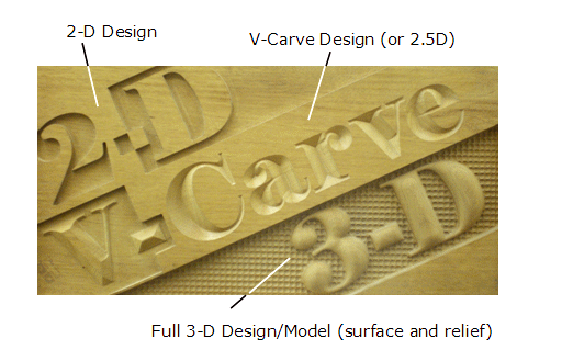
Rich has a good point — the design with its need for a minimum of 4 colours is not well-suited for V-carving.
Unfortunately, Windows crashed and I lost the tutorial aspect of what I was working on — the short version would be:
Not quite finished, but here’s a re-drawn version which I leave as an exercise for the reader to finish processing in Inkscape, scale appropriately for import, then work out CAM operations.
From one 80132 to another.

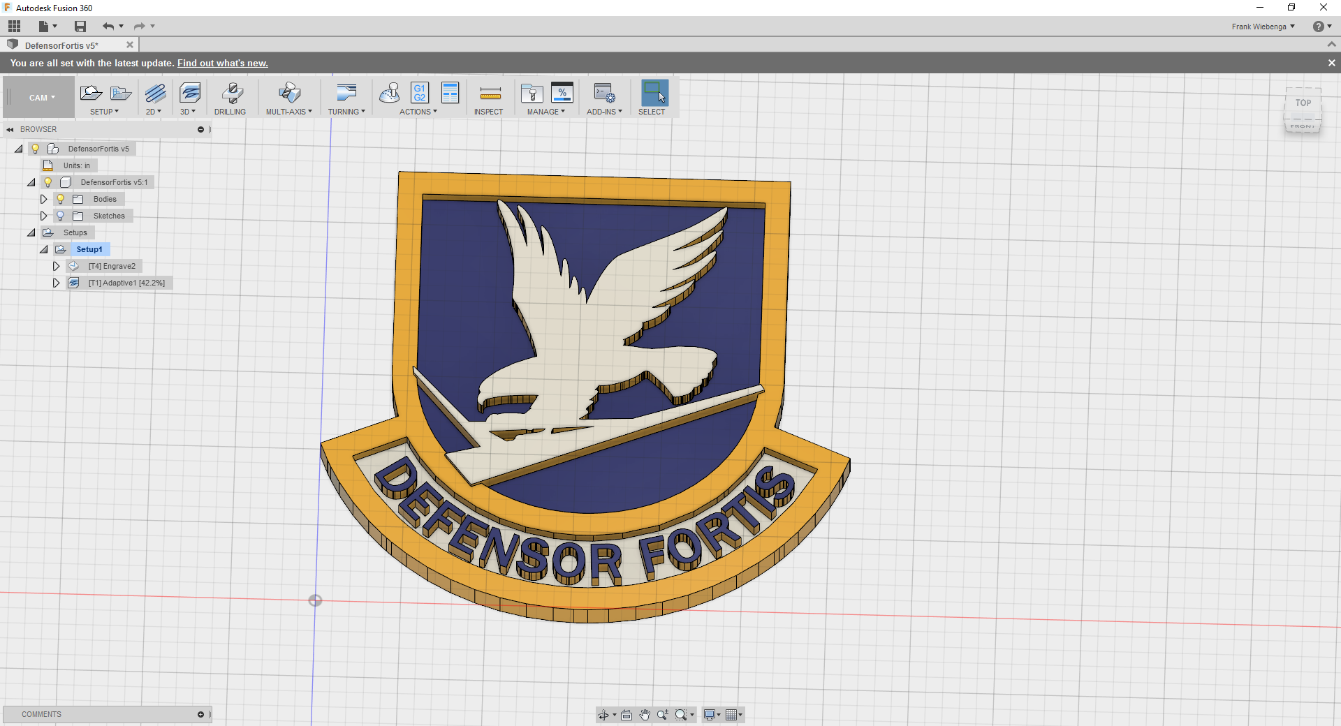
Quick and Dirty, Start with one @WillAdams vector file instead of how I did it. By no means ready to run.
My method to madness
DXF & Carbide Create File
Defensor Fortis.zip (190.2 KB)
Looking at that, I’m kind of mystified as to why the runways project past the shield.
Looking at my re-drawing, it’s got at least one definite error (confusion of wings between front and back, also not wild about what look to be mis-shapen tail feathers along lower edge…) really wish there was a better original…
EDIT: and as noted below, there was, I simply missed it last night and this morning in @atrueresistance 's post. In my defense, I’m pretty sure that I tried visiting that site from a search last night and it wasn’t coming up.
Only spend a half hour in Fusion. The online dxf converter didn’t do the greatest job. Is the site I referenced for the eps the original copy?
I’m not a military man, so just took my best guess.
That’s the right place, and a site I simply wasn’t finding last night (hence my re-draw).
I’ll look at how it’s put together and see what I can do w/ it.
Thanks!
It might be best to start with the black version; I was only able to find a PDF.
I also quickly did it up in Easel- http://easel.inventables.com/projects/t3Sqmscg7zETn0ESZMFBsA
Because of the detail, you may have to use a 1/32" bit for some areas (e.g. the talons). The other option would be to not union all the paths (just the arrow and shield) and cut things to different depths.
~Kenny
Non-unioned paths:

Unioned paths
Misliked that one part didn’t get a white outline, and thought it’d work better for engraving inverted.

.
Belike the easiest way to cut this would be to d/l and install F-Engrave, then add the attached font to the F-Engrave fonts folder, then set the desired height.
AFSS.zip (11.2 KB)
Documentation on F-engrave here: http://www.shapeoko.com/wiki/index.php/F-Engrave
is there an f engrave for mac users?
Okay, trying again, let’s do this step-by-step w/ detail suitable for a tutorial:
Open the .pdf in a suitable vector editor (I selected Inkscape) and switch to outline view — View | Display Mode | Outline
(optional, Inkscape affords an option to automatically set the page size to match the drawing, File | Document Properties | Resize page to drawing or selection — this was done here to make for a consistent sizing and placement of the image)

Note that there are a number of instances of over-lapping elements — these must be addressed so that the image can have toolpaths applied w/o interfering with other elements.
When selected, the image is a Group — ungroup until the image is composed of nothing but paths — there should be 42 of them.
Then, select paths which overlap, duplicate the one which you wish to subtract from the other, select the second path and Path | Difference until all such overlapping is eliminated. When viewed in Normal mode, the appearance should be much the same as the original:

However, when viewed in outline mode, one sees only that geometry which one would wish to have cut:

At this point, the file is usable for V-carving, if there is no need to consider the matter of how wide the V-bit is, and how deep it will cut (the piece would be very small), or if the CAM program used for V-carving has a facility to limit the depth to which it will cut. That is not the case with Carbide Create, so some additional planning, math and geometry are necessary.
The first thing to do is to decide what elements will be cut to what depth:
Then, we must decide:
For this tutorial:
The first thing to determine is what width a 90 degree V-bit will cut at a depth of 1/8" — this is easily determined using trigonometry, or may be determined by drawing up the relevant geometry, or realized easily when one notes that the projection of a 45 degree angle at a given depth results in one-half of a square, so the width offset is the same as the depth to which we will be cutting, which greatly simplifies the math.
At this size, there is no need to depth limit the space around the letters.
By request, the letter portion of this was done on the Shapeoko forums:
and the beginnings of a wiki page were made: http://www.shapeoko.com/wiki/index.php/Carbide_Create_V-carving_(advanced)
Revisiting this again:
Okay, trying again.
Re-drew the pocketing and other areas to arrive at something like:
