Help with vCarving a sign

Rich has a good point — the design with its need for a minimum of 4 colours is not well-suited for V-carving.

Unfortunately, Windows crashed and I lost the tutorial aspect of what I was working on — the short version would be:

  • place image on background layer, dim it and lock it
  • re-draw the object, starting with the background, creating an additional layer to store geometry on for re-use — duplicate items from it at need
  • simplify the file representation as much as is possible — create geometries which will match what you wish to carve

Not quite finished, but here’s a re-drawn version which I leave as an exercise for the reader to finish processing in Inkscape, scale appropriately for import, then work out CAM operations.

From one 80132 to another.

3 Likes

Quick and Dirty, Start with one @WillAdams vector file instead of how I did it. By no means ready to run.

My method to madness

  1. Download .eps from here.
  2. Use cloud convert to convert it to DXF.
  3. Import into Fusion 360 (attached file) or Carbide Create.
  4. Create your toolpaths/geometry in either program. (use more conservative depth/step then what is in f360 example)

DXF & Carbide Create File
Defensor Fortis.zip (190.2 KB)

Looking at that, I’m kind of mystified as to why the runways project past the shield.

Looking at my re-drawing, it’s got at least one definite error (confusion of wings between front and back, also not wild about what look to be mis-shapen tail feathers along lower edge…) really wish there was a better original…

EDIT: and as noted below, there was, I simply missed it last night and this morning in @atrueresistance 's post. In my defense, I’m pretty sure that I tried visiting that site from a search last night and it wasn’t coming up.

Only spend a half hour in Fusion. The online dxf converter didn’t do the greatest job. Is the site I referenced for the eps the original copy?

I’m not a military man, so just took my best guess.

That’s the right place, and a site I simply wasn’t finding last night (hence my re-draw).

I’ll look at how it’s put together and see what I can do w/ it.

Thanks!

It might be best to start with the black version; I was only able to find a PDF.

  1. Using pdf2ps I converted to a postscript which let inkscape see the vector drawing as paths.
  2. Opened converted ps in inkscape, selected everything and then Path:Union; this removes the arrow artifacts show in @atrueresistance’s image.
  3. Save the new modified file as an SVG. (Available below)
  4. I don’t have carbide create on this computer, but it should be similar to the makercam steps…
  5. Open the SVG file in makercam
  6. Draw a rectangle of appropriate size (Insert: Rectangle)
  7. Scale svg (Select it, then Edit:Scale Selected, 150% fills a 10" square nicely)
  8. Select everything, and create a pocket operation (CAM: Pocket Operation)
  9. Set appropriate tool diameter, depth, etc.

I also quickly did it up in Easel- http://easel.inventables.com/projects/t3Sqmscg7zETn0ESZMFBsA
Because of the detail, you may have to use a 1/32" bit for some areas (e.g. the talons). The other option would be to not union all the paths (just the arrow and shield) and cut things to different depths.

~Kenny
Non-unioned paths:

Unioned paths

2 Likes

Misliked that one part didn’t get a white outline, and thought it’d work better for engraving inverted.

.

Belike the easiest way to cut this would be to d/l and install F-Engrave, then add the attached font to the F-Engrave fonts folder, then set the desired height.

AFSS.zip (11.2 KB)

Documentation on F-engrave here: http://www.shapeoko.com/wiki/index.php/F-Engrave

1 Like

is there an f engrave for mac users?

http://www.shapeoko.com/wiki/index.php/F-Engrave#Mac_OS_X

Okay, trying again, let’s do this step-by-step w/ detail suitable for a tutorial:

Open the .pdf in a suitable vector editor (I selected Inkscape) and switch to outline view — View | Display Mode | Outline

(optional, Inkscape affords an option to automatically set the page size to match the drawing, File | Document Properties | Resize page to drawing or selection — this was done here to make for a consistent sizing and placement of the image)

Note that there are a number of instances of over-lapping elements — these must be addressed so that the image can have toolpaths applied w/o interfering with other elements.

When selected, the image is a Group — ungroup until the image is composed of nothing but paths — there should be 42 of them.

Then, select paths which overlap, duplicate the one which you wish to subtract from the other, select the second path and Path | Difference until all such overlapping is eliminated. When viewed in Normal mode, the appearance should be much the same as the original:

However, when viewed in outline mode, one sees only that geometry which one would wish to have cut:

At this point, the file is usable for V-carving, if there is no need to consider the matter of how wide the V-bit is, and how deep it will cut (the piece would be very small), or if the CAM program used for V-carving has a facility to limit the depth to which it will cut. That is not the case with Carbide Create, so some additional planning, math and geometry are necessary.

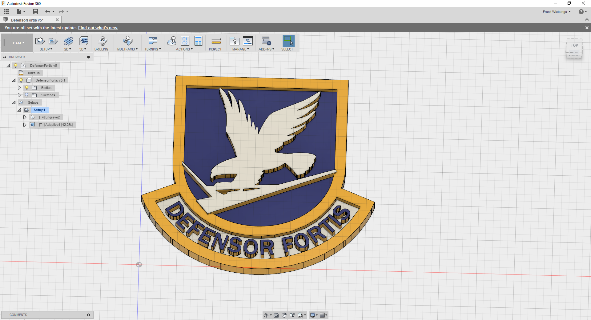
The first thing to do is to decide what elements will be cut to what depth:

  • the outer gold, and the blue letterforms will be left full height
  • the white surrounding the letters may be a normal V-carve (if sized so that the bit can plunge fully into the piece to cut the widest element
  • similarly the gold of the feet will be left at full height
  • the black of the talons will be left at full height, but pierced by a simple V-carve
  • the grey will also be left at full height
  • the white areas will be recessed to half the intended cut depth
  • the inner blue areas of the shield will be cut to the full cut depth, and the sharp corners and inner edges will be will be V-carved so as to increase their definition — this will leave some areas which will need to cleaned up w/ a chisel

Then, we must decide:

  • what size the piece will be cut to
  • what the thickness of the stock will be
  • what the greatest depth to which we will be cutting
  • what angle V-bit will be used

For this tutorial:

  • 5" wide
  • 1/4"
  • 1/8"
  • 90 degrees

The first thing to determine is what width a 90 degree V-bit will cut at a depth of 1/8" — this is easily determined using trigonometry, or may be determined by drawing up the relevant geometry, or realized easily when one notes that the projection of a 45 degree angle at a given depth results in one-half of a square, so the width offset is the same as the depth to which we will be cutting, which greatly simplifies the math.

At this size, there is no need to depth limit the space around the letters.

By request, the letter portion of this was done on the Shapeoko forums:

and the beginnings of a wiki page were made: http://www.shapeoko.com/wiki/index.php/Carbide_Create_V-carving_(advanced)

1 Like

Revisiting this again:

  • simplify by cutting to same depth
  • cut all features save for outer border (and the letters, and prob. the feet) — fill with pigment
  • file / plane off after cutting so as to create highlight lines separating regions
1 Like

Okay, trying again.

Re-drew the pocketing and other areas to arrive at something like:

Wow making progress I’d love to see this to a finished file I just don’t have the knowledge or experience to get it there…Thanks for working in it

Almost there:

Unfortunately, failed to:

  • add additional geometry for the outer profile to allow V-carving the perimeter
  • remove the grey highlights from the white area of the bird
  • properly separate the white areas of the runway

Anyway, the basic principle is to:

  • calculate how wide an area one needs for V-carving to the desired depth
  • add an inset along that centerline
  • adjust both paths so that things are rounded off so as to eliminate peaks

Would it be possible/ easier to cut the interior around the eagle and runways out completely with a straight bit?

It would depend on the scale and size of the bit relative to the piece. Basically inlay options go this way:

  • straight bit, inlay with vertical sides
  • smallest detail limited by endmill diameter
  • any narrow feature must be at least endmill diameter+10%
  • V-carve with angled sides — through cut
  • all inlay pieces must be same thickness
  • detail limited to one’s workholding ability / options / patience
  • V-carve inlay with pockets
  • requires specialized software or careful toolpath planning

But with a bit of patience, it works:

small_separated_two.c2d (1.4 MB)

2 Likes

Is there a way to stop it from cutting all the way through?

Further adjust the paths, or use a tool which limits depths, or use a shallower angle tool, or a thicker material.

I figure I’ll just fill w/ powdered enamel and epoxy.

Anyway, finally found time to cut this w/ the right endmills:

Need to get a loupe from work and deburr the edges and then work out some way to infill the colours.

2 Likes