So I’ve had my Nomad for quite a while but haven’t had a chance to do anything with it until now. I created a part to make a mold from. I tested milling it out of wax and at first everything looked great. However, when the job was complete I noticed that the holes came out more oblong than round (longer in the x-axis). Also, halve a cylinder in the top is milled out and is not completely correct either. Again it looks like it’s out in the x-axis. I used the carbide auto toolpath in Meshcam and didn’t change any of the settings.
The red arrows show the holes out of round. The small hole is 5mm and the larger hole is 6mm. I am used an 1/8in ball end mill. The green arrow is pointing to the half cylinder that is milled front to back (.25 diameter).
I tried to run a simulation on it but unfortunately I’m running a mac and can’t see how to do it. Perhaps it only works on the windows version. I found a free program called CAMotics and it seems to show the the correct motion.
I’m not sure if this is due to baclash or perhaps milling too fast. I tried it again and only milled the one end of the part. I didn’t change any meshcam setting and for some strange reason it improved but was still noticeable.
Welcome @PDG! The forum is here to help and inspire.
From the clear pictures you’ve posted, I would first suspect a fixturing problem - the stock (wax) is moving around while being machined.
The Nomad has excellent repeatability - 0.001" - so unless this is rather extreme magnification I would not expect backlash. It’s possible that there is a physical issue with the Nomad but let’s start eliminating issues before we go there.
Can you post a screen capture of your MeshCAM parameters? If the issue is “feeds and speeds” that will tell us what’s going on.
I found a free program called CAMotics and it seems to show the the correct motion.
A good choice. I use GW-Editor, a commercial product, but there are many similar programs to choose from. NCPlot is another good commercial choice.
I’ll give it another shot. My first attempts were to remove the waste board and I used the provided double-sided tape to stick the wax to the bed. It seems to be quite solid but I’ll try and use a vise instead.
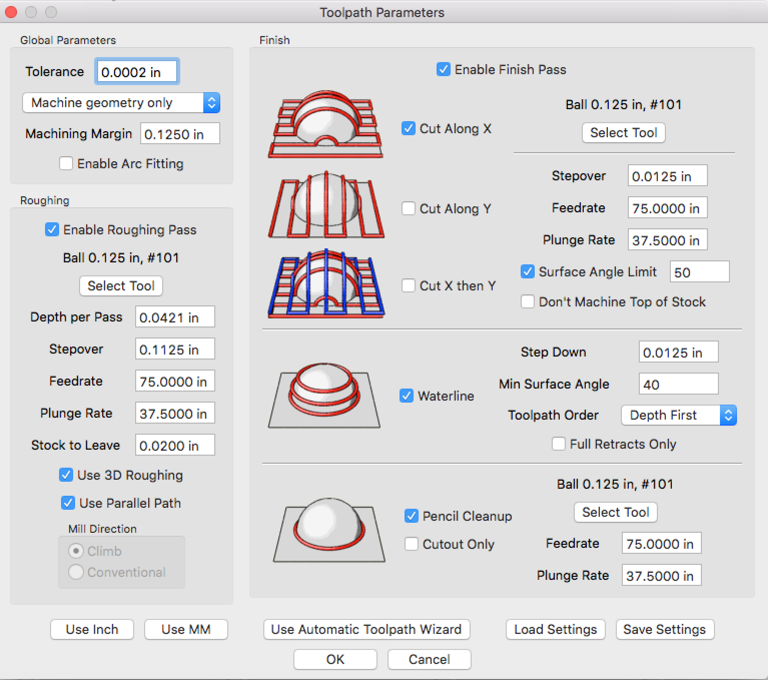
Here are my settings. I didn’t change anything from what was automatically set.
So I tried it with the same setting without tape. I used the vise. It was marginally better but the problem still exists. I was watching it during the milling operation, and on the very final move ( I believe that is the pencil finish), it appears to plunge and do the final circular motion at an extremely aggressive rate. I know the settings are the same but, perhaps because it is a larger cut it seems really fast. Up until this final cut, the holes appeared to look really good. This final cut is where they go out of round. So, I’ll try again with the setting you recommended and see how it goes. Thanks.
I’m not sure I understand entirely how MC interprets the settings. I opened up the tool settings for my 101 ball endmill. I see the default settings are 5 IPM and spindle speed is 4687 RPM. I assume that the 75 IPM in the toolpath parameters overrides the tool settings of 5 IPM. But, I don’t see anywhere to override the RPM to 10K. Do I change this in the tool settings? I would have thought that you would be able to adjust this in the toolpath parameters as well.
I assume that the 75 IPM in the toolpath parameters overrides the tool settings of 5 IPM.
Correct.
I would have thought that you would be able to adjust this in the toolpath parameters as well.
Me too. If there is a way I haven’t found it (yet?).
In MeshCAM, as I understand it, one lands up with an entry for each end mill AND material. @Randy may know more… I’m awaiting my Nomad and MeshCAM license.
Many CAM packages have no feed/speed data in their tool list. It’s entered with each cut - the last entry is remembered. Fancy ones remember feed/speed data based on the material involved, not the tool itself.
I would love to see a table of just tools and tool characteristics… and a comment field. Another table of materials… and a comment field. A third table that “joins” a material entry with tool emtry. Feeds and speeds are there… and a comment field. Identify the material one is CAMing and the default values are those from the “joins” table.
Even better, let me override the feed and RPM from the “joins”.
The wax feed for 4700 RPM is 37. Plunge 1/4 of that.
I’m using G-Wizard, with Nomad characteristics entered, to get these numbers.
Hi. Not sure this is exactly your problem, but it kind of looks like the one I and some others had a long time ago. I thought they fixed it with more recent Nomads but you said you had your for a long time before trying anything so maybe there’s something here:
We had issues where the X axis would drift over time. For me it was always to the right - I think this was the case for the others who had this problem as well. So what happens is as your workpiece gets milled out at lower and lower Z values, all of the walls facing towards the -X direction (the right sides of all your holes) drift further and further right as the endmill crashes into the entirety of the wall-previously-cut and shaves away the whole wall by however far it’s drifted since the last pass - meanwhile all the walls facing the +X direction end up stairstep tapered as the endmill drifts away from the wall at each pass.
So for a hole, like yours, you’d expect it to be too large in X, with one of the sides tapered (hard to see from your photo of the two deep holes, but the side view looks like I would expect (the drift would be to the left in that image, so either your drift is reversed or that image is of the back wall, not the front).
Here are the pictures of what my tests looked like so you can see the artifact you could expect from this issue:
If you follow that megathread you can see other people’s issues (ignore the scalloping on the head shape, but the rest were legit I think), and how it got fixed - if this is indeed your problem I think it is an easy fix.
If you want to repeat my test you can use one of your 3x2x1 blocks of wax or Renshape and run it on my test files, here:
(answering @mbellon above–I don’t know how to quote)
The MeshCAM tool library has presets for speed, feed, stepover, stepdown. They are just static numbers you enter when you define a tool. They will appear as defaults in the Toolpath Parameters dialog when you select a tool for the operation.
The Carbide license of MeshCAM has a wizard that takes into account the cutter, material, and Nomad capabilities and overrides the numbers in the tool library when you use the wizard. But it also just fills in the boxes in the Toolpath Parameters dialog.
The numbers in that dialog are what is used in writing the gcode. You can edit them, and if so than your hand-typed values are what goes into the gcode.
@kjl Thanks for the input. I’ve verified that the problem is definitely happening in the +x direction. I’ve emailed support to see if they will replace the board.
I’m having this same issue with acetyl and I assumed it must be the steppers slipping because i was going too fast. After reading some of this thread though I’m not so sure.
Interesting, I think I might have to send some photos too them too. I thought it was just my cutter moving too fast in acytal but I had used slower than the recommended feed rates so now I am seriously wondering if this is my issue too. I have a new board I got as a spare so I might run a few more tests with slow feed in soft material. If I see the same issue I will look at replacing the board for the spare I ordered. If it is the same issue then hopefully carbide will come to the party and replace my spare. They seem to be very good with customer support!
Well I guess it’s too early to know for sure but it looks like I had the same issue. Luckily I got some spares not so long ago. One of them was a board.
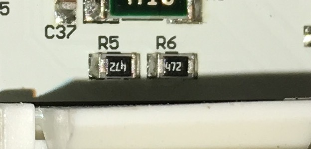
Original Board
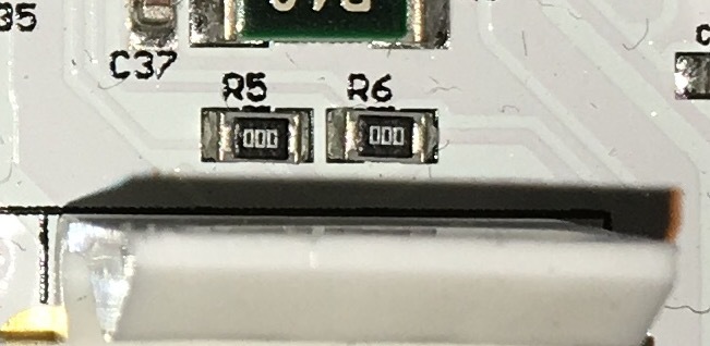
Spare Board - note resistors are all just bridges (0ohms)
Fast - ‘low tollerance’ test run after fitting new board. Accurate to 0.1mm over depth of cut of 7.62mm.
C3D sent me a new board last week. I finally replaced it yesterday and I’m happy to report that this did indeed solve my problem. I ran the same program again and my holes came out round and there was no “stutter steps” on the positive x side. I appreciate all of the input from the community and really want to thank @Jorge for getting back to me and responding to my request without hesitation. Great service and support from Carbide 3D!