How to make a part that is too large for the machine

This is going to come in a number of parts as there are a lot of details involved.

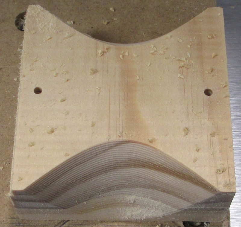
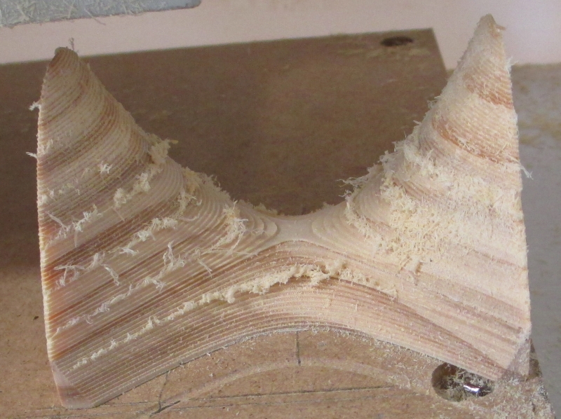
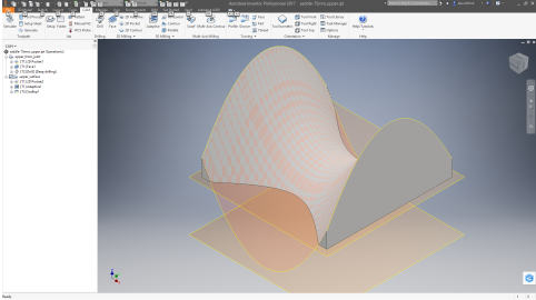
First, the reason: I needed to make some pars that are too large for the Nomad in the Z orientation. These are not mission critical for a NASA launch level parts, but they are to roughly 0.05mm (50 micron) for most dimensions. They will be done in aluminum, but for the proposes here, I went with an abstract form (hyperbolic paraboloid: F(x,y)=(x^2-y^2)*37.5mm, -1<=x<=1, -1<=y<=1) for practice, and ran it in wood for speed. And because it will be pretty. I ran it once for debugging, and a second time to demo for a student, so documented for y’all as well.

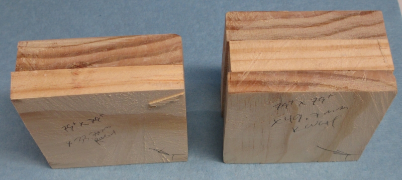
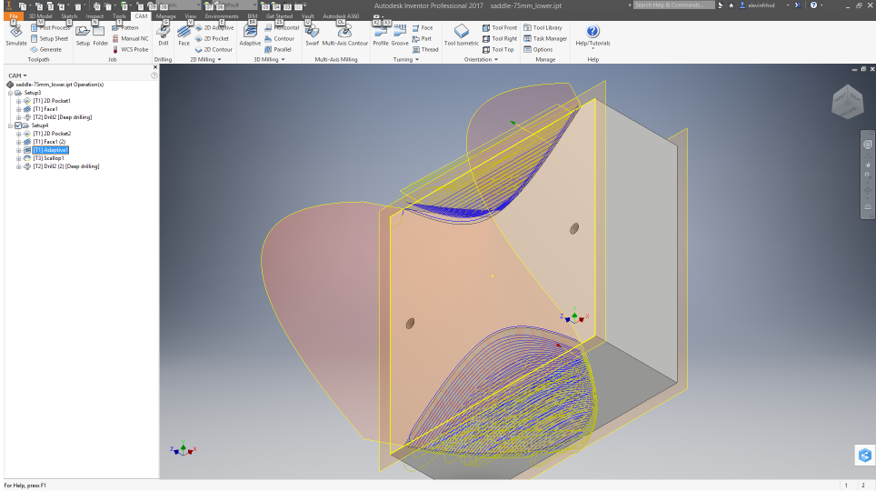
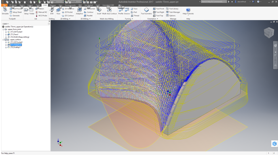
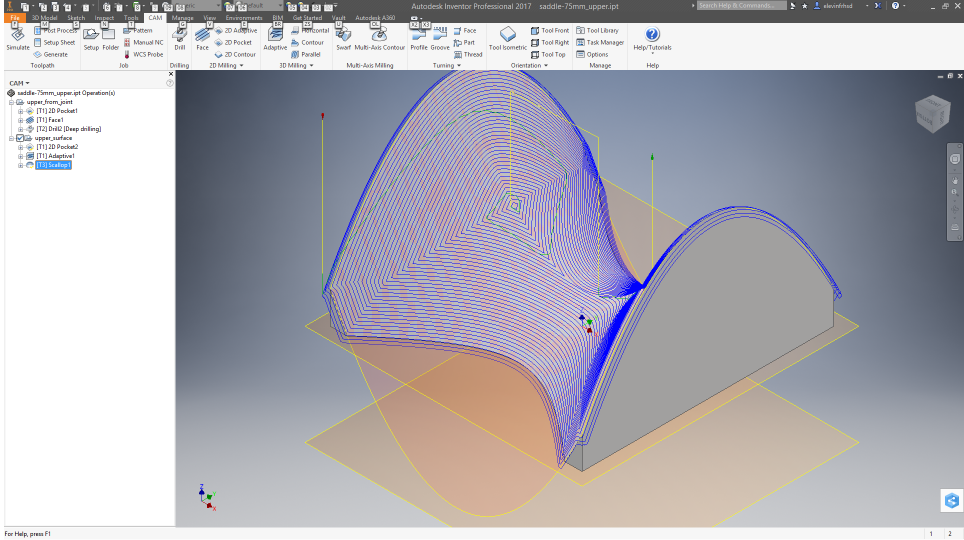
The starting point: Though the machine has about 85mm clearance between the bottom of the Z carriage and the baseplate, about 70mm between the top of the table and the bottom of the Z carriage, and about 90mm of Z travel, it is generally not practical to work a piece taller than about 50mm, especially if the machining will be full thickness. Tool clearance and extension, and spindle clearance become issues fast, even if the material is cleared by the Z carriage. This example is for a part that finishes to 77mm in Z (and 75X75 in x-y) In planning, I constrained to maximum tool extension for a 1/8" (3.175mm) diameter tool at 30mm, which is roughly 10D, which is pretty long and about the practical limit, even for a small carbide tool in a good collet.

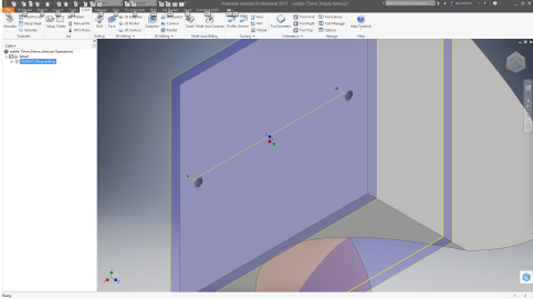
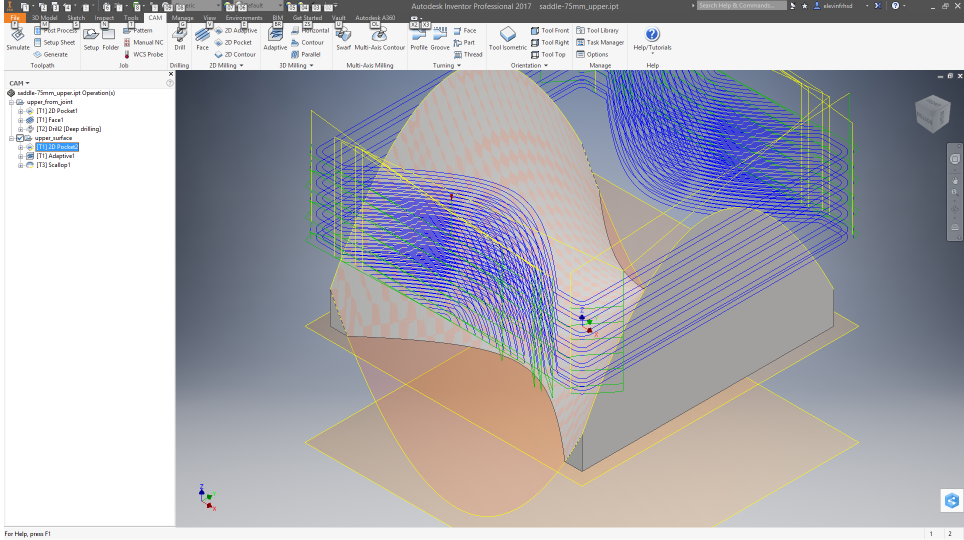
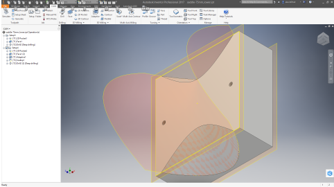
The model was done in Inventor (the real parts will be worked in Inventor and AutoCAD):

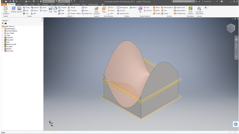
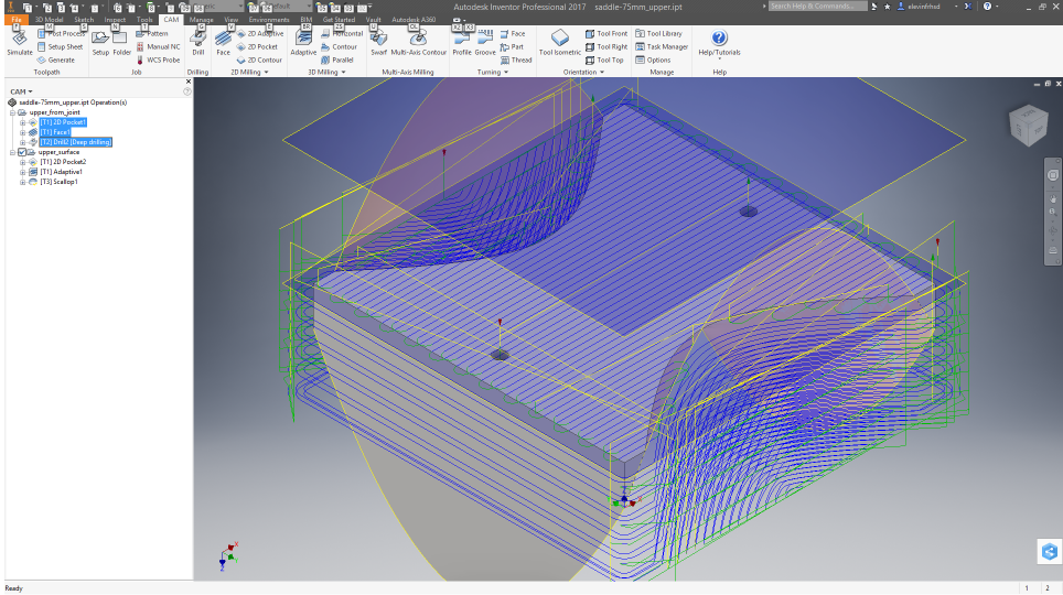
The entire Z range is used for finish surfaces. There isn’t clearance in some places for the collet nut if the tool is held short enough to get to the top, so precise tool repositioning would be needed mid job, and there would be no guarantee that the tool wouldn’t be dragged through the part during a homing or probe cycle. That is presuming that the stock was taped directly to the stock table plate so that the Z carriage would clear it (by a couple mm).

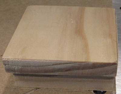
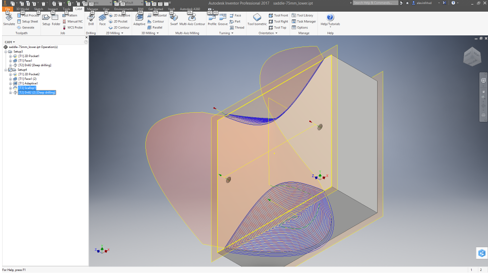
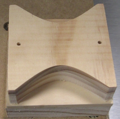
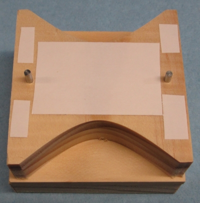
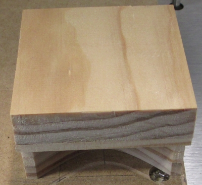
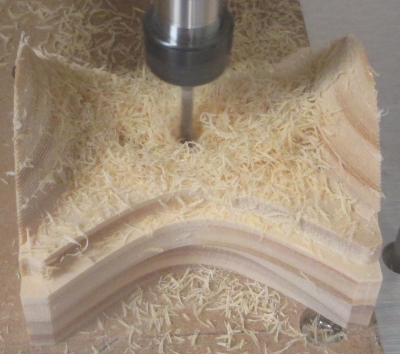
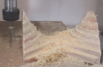
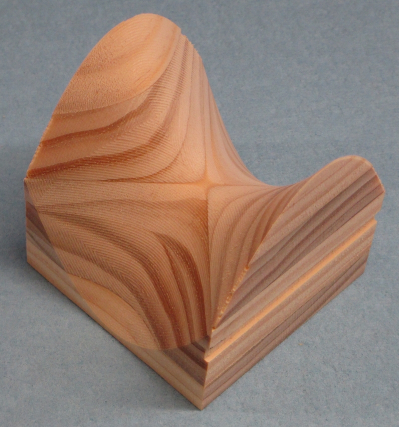
So I split the model into two parts. The plane just under half way up is the cut plane.

The position was selected so that the upper part would have enough material tying it together. If the cutting plane was at mid-Z, then the upper part would not have significant material to hold it together, and the job would be more complex, but be done using the same techniques.

This led to two parts to machine:

model_lowermodel_upper

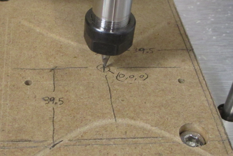
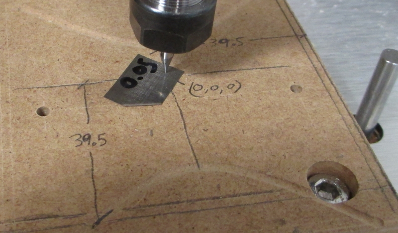
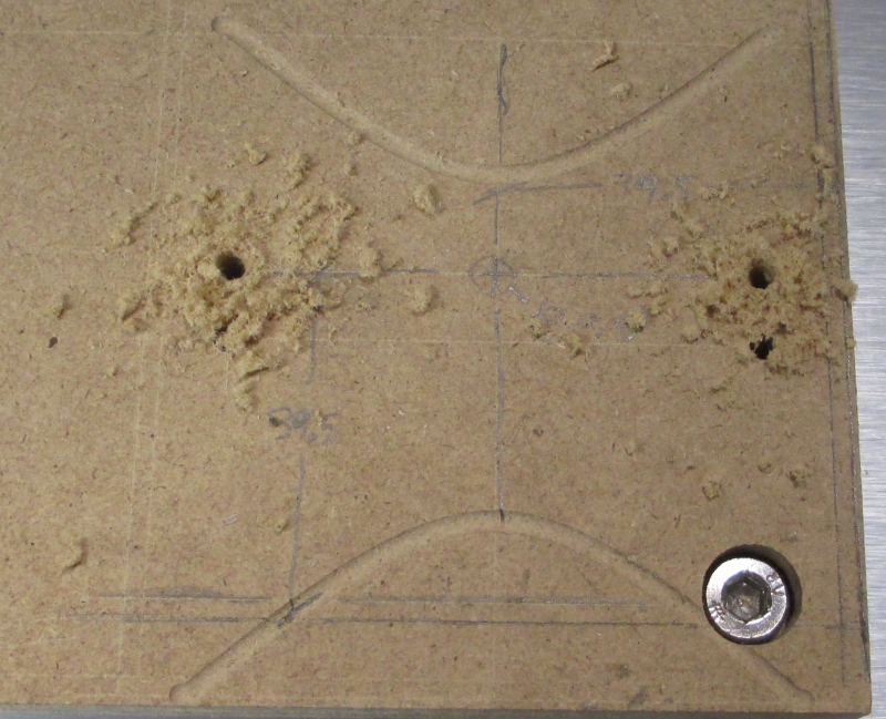
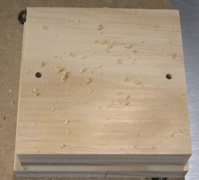
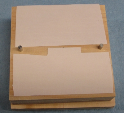
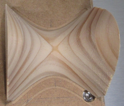
The split was done by deriving two models, one for the upper and one for the lower. The holes visible in the lower part were in the original model, run from the bottom until they nearly broke the top surface. This insures alignment, and they are used both for machining and for assembly.

3 Likes

The first thing done once the model was complete and split into two parts was to decide on a reference frame for the machine work. The origin was set for all operations as the center in x-y at the table surface, so the bottom for all operations is z=0.

This NEVER GETS CHANGED. Once it is set, ALL parts of the job are run without changing the machine zeroes. This is because the first operation is to bore alignment holes in the wasteboard.

model_fixture_holes

The bottom of the original model is used for this. The alignment holes are 3.00mm because that is a convenient size dowel pin I keep on hand. (3mmX12mm long) The holes are bored about 7mm deep.

The setup for this is the only fussy part of the process. First, I laid out the part and the stock profiles on the wasteboard using a caliper (the pencil marks are handy, but primarily for clarity in the pictures)


The x and y zero was eyeballed using a little magnification, as it is not critical, but the z was zeroed by bringing a point tool down to a 0.05mm feeler, then bringing it down the last 0.005 to set zero. You can see the residue of the first test piece in the wasteboard.

The stock was prepped by epoxying up a stack of white pine then handsawing to size. More than good enough as I allowed 2mm all around stock allowance (and 3mm in Z) Then the squarest corners were selected for reference

There was no particular concern for dead flat or square. The whole surface will be cut by the machine.

First, the lower part was machined. This was done in two setups.

The bottom surface first:

The material was taped down in alignment with the layout on the waste board.

The perimeter was cut to about half of the Z depth of this part and face the surface.

IMG_0682

Last, two 3.00mm holes were bored 7mm deep for alignment for the next operation.

The part was removed from the wasteboard and remounted using the dowel pins to align it.

IMG_0684IMG_0685

This side required finish profile, so not only was the outside profiled and the top decked, still using a flat end mill, a rough (trochoidal) rapid profile was done at about 1000mm/min (slow due to long tool stickout) leaving about 0.1mm.


Then a finish pass with a ball end mill and drill alignment holes to get

(the rebate on the left is due to a toolpath mistake I made.)

Now comes the top piece, also in two setups:

In this case, the profile done from the bottom took a lot of material for the final profile, rather than just square the sides. Again, the layout on the waste board was used to position the material and tape for holding it down.

IMG_0690

The part was removed and refit using dowel pins for alignment:

IMG_0691IMG_0692

The operations for the finish side were similar to the bottom section. outer profile, trochoidal roughing, then finish. No deck was done since the entire topside will be finished using the ball end mill.

I took care to insure that the roughing worked in from the rear where possible:

IMG_0693

This is REAL nice for chip and dust control. Most of it stayed on the bed for easy removal periodically during the job.

There was a real risk of crashing through the part.

IMG_0698

The final rough looks like

The finish pass with the ball end cleaned up to the bottom edge, so it also cut into the waste board. The very edge was run as a shallow waterline first to get some of the material out of the way and reduce tool deflection. The tool was out 27mm. If I shortened to 25mm, the collet nut would hit the edge of the part.

IMG_0703

The final product is assembled using the same dowel pins as for setup.

The final assembly, in wood, came in at about 0.06mm, in large part because the dowel holes stretched a little.

The alignment between the operations for each part was a little better, at about 0.04mm.

Once the parts are epoxied together, a light sanding and finishing will be done. The only evidence left of the technique is the two fixturing holes in the bottom. A little chipout on the thin edges in the croos grain section, but it will go away when the edges are softened during sanding.

By the way, I did try to get the glue joint between the grain directions to land exactly at the saddle point, but I missed by about 0.3mm. It still looks fine.

4 Likes

The key to getting a good product in the end is planning. I wright the job sheet as the operations are developed and add notes as needed to avoid careless mistakes. For this job, the sheet was

Each operation and tool is listed, as is fixturing, tool ID, tool lengths, and so on. It can be done more formally, but this is often all that is needed. The setup sheet from the cad system can be printed, key things highlighted, and notes added, but I can do this while building the job. I still run the setup sheet from the cad system as a check.

5 Likes

Your comment in op1 says “DO NOT REUSE IF ORIGIN IS RESET”. Did you find that homing isn’t accurate enough, or do you not have homing switches?

Neat technique, thanks for sharing.

CM doesn’t provide a way to store work offsets/zero for later recovery. The homing and tool probing is within 0.02mm in my experience, but if I run another job (in this case I ran a couple between the first piece and the one I used for demo, each with its own zero) then they need to be reset. In this case, for the demo, as I had removed the waste board and reinstalled, as well as reset the origin for other jobs, the alignment holes from the prior run had no guarantee to be in the same place.

I’ll sometimes write down my set origin coordinates (from homing position) just in case I lose it because of a CM glitch or what not. If CM does lose it, I’ll home the machine and jog there with a manual g-code command.

1 Like