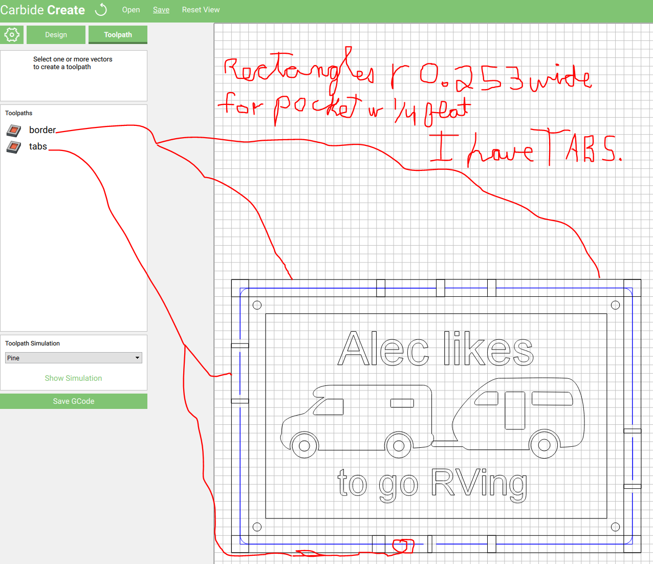
Reading a lot, read a topic from last year requesting tabs as a feature, I am new to CNC and by no means am suggesting this as a how to but more as a IS this how to make tabs. I dare not try to open a gcode and am desiring to contain my lack of knowledge and my emphasis on learning one software at a time so makercam and inksplot (as I would transgress in it) are not in my equation. I want tabs, as most others do, CC can’t do it. So I am simply stating this is how I did it in CC and it appears to work in simulation view. (ps I don’t have my machine yet) . I don’t know if this is more work than it is worth and I dare not try to explain my process to such extremely experienced and knowledgable folks as yourself ( this is respect not sarcasm). Please look at the uploads and you will know about how I did it than I do (I am sure). I did use 0…253 as a rectangle width and pocketed the border because of another topic I read aboutoverlap rect corners making tabs.c2d (413.3 KB)
I’m concerned about no replies, I sincerely hope I didn’t offend the forum. If I did I’m sorry. I’m a 60 yo recluse who doesn’t social network (not an excuse). Anyway I have been learning CC while I await my machine and have been testing my thoughts.
Here’s another approach, rectangles that are ,001 in width and 1 in long joint at the end for the corner of the border. Copy rotate for each other corner. There could be several lengths to choose from. Also anther 1/2" rectangle for a “tab”. I “cut” these with a “no offset” and a 1/4" bit and CC wrote a good tab in simulation. Could these “design elements” be imported into the design elements library? I also took one border rectangle and copied it overlapping over the corner rectangle to extend the corner rectangle without the need to draw more .001 wide rectangles. the simulation showed a continuous cut from the overlapping rectangles. Until CC has tabs, this is the only way I have been able to “build” them.
The consideration of leaving a skin and cutting small parts for my toys will cause too much tear out, in my opinion2 inch border and half inch tab 001 wide rectangles.c2d (10.2 KB)
and corner rect copied and overlaped top n bottom.c2d (15.3 KB)
You got two likes, which is a lot for here — I also meant to, but failed to link your post to the Carbide Create wiki page — going to go do that now.
I’ve said in the past that one can just draw in the geometry to make tabs by hand — very nice to see someone do so!
Thank you Will. I feel productive. I read your post of creating tabs with inkspace but wanted to stay pure CC. I noted my topic in a feature request topic asking these rectangles be added into the design element library, for now I open that drawing as a starting point in CC. Happy New Year !!!
Hey Jude,
Welcome to the forum!
I like your approach to adding tabs to a part in Carbide Create!
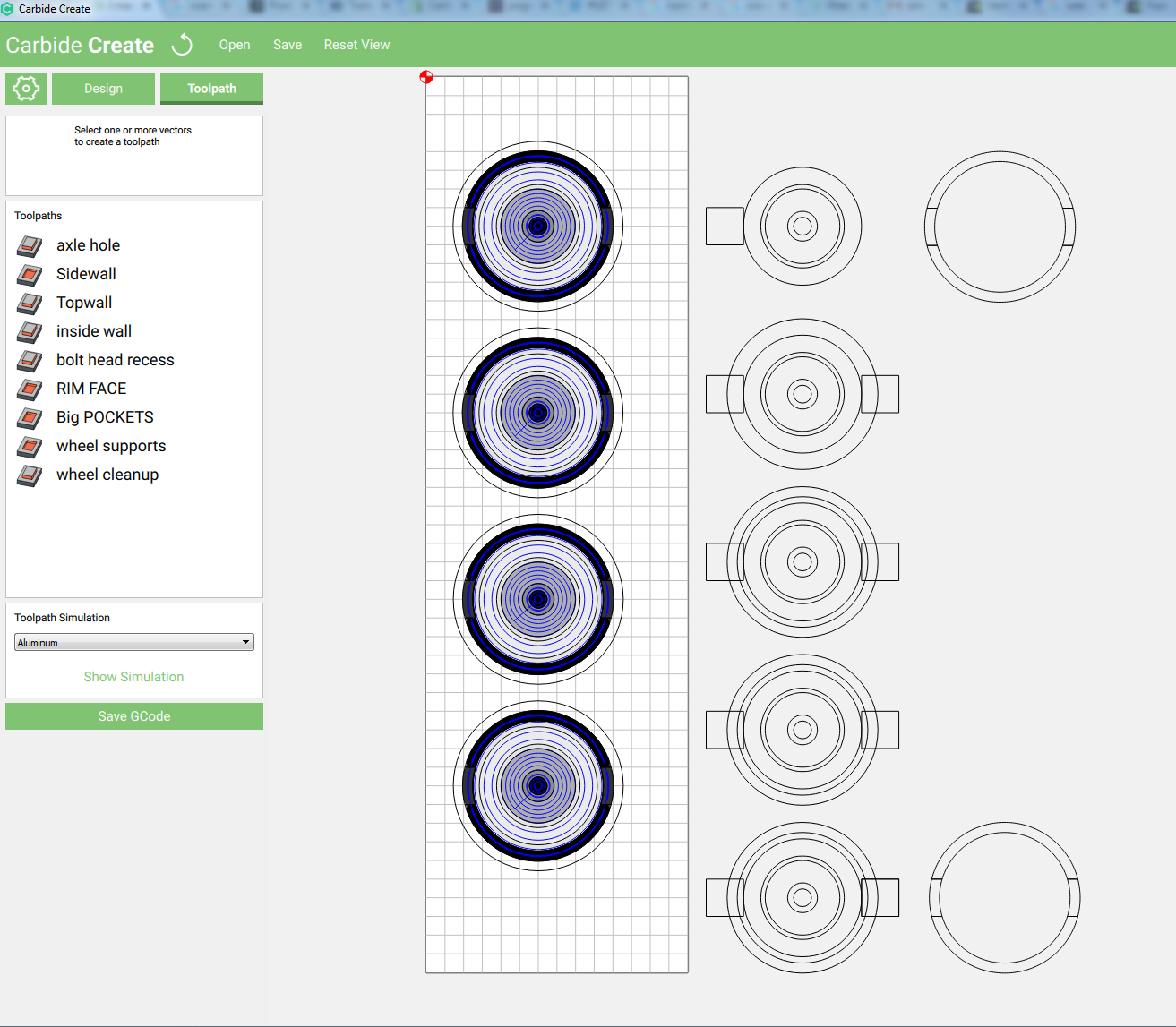
Heres a Set of wheels made using a similar approach:
Toy Car Wheels with tabs.c2d (1.3 MB)
By Selecting multiple shapes and using the Boolean cut/join options you can slice or compound shapes and stack them with different cut depths:
Design Preview
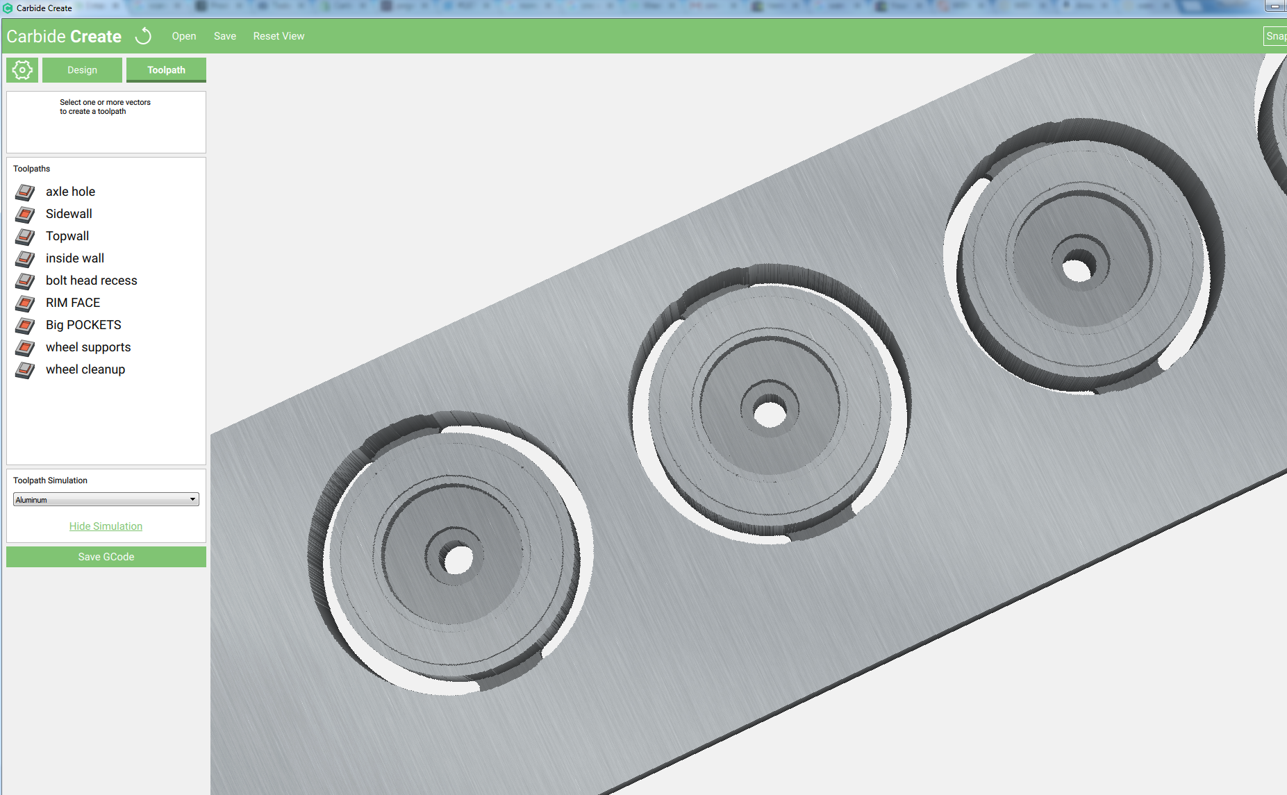
Toolpath Preview
Thanks Apollo, I’ll check this out, but right now I have 300 + wheels in stock and I’m building rubber band guns. I read another member building them also. Reading is FUNdamental.
learning continues, in the toy wheel design, “big pockets” are the cut out around the wheel, “wheel supports” are the tabs and “wheel cleanup” is an outside cut because a pocket obviously is not a “finish” cut to cleanup the edge of the wheel without cutting the tabs. Thanks.
Thank you for your suggested workaround to this missing Carbide Create feature. I can see where this method would work for poly objects that can be easily scaled up to a second boundary object, one cutter width size larger all around than the original, and broken into pieces so a pocket toolpath can be created rather than an outside/right path to leave “tabs” and remove most of the material around the object to be cut completely free. However, having tried it for real when making components for a wooden clock project its still a significant design effort, if I understand your methodology correctly, and much more time consuming if the poly object has indentations, for lack of a better word, since the original boundary of the object cannot be simply scaled up.
Many of my parts have this problem and for this reason I’m looking at spending $ for a program capable of auto-creating the tabs and easily re-positioning them (Trialing VCarve). If I knew Carbide Create had this feature scheduled to be released I would hold off. It’s too big a deal for me to wait indefinitely on though. I can’t walk more than a few arms length away from the jobs right now without worrying about how close the part is to being freed and the part being destroyed or damaged. I’ve tried the Winston Moy suggested double sided tape, and I’ve tried leaving a few thousands of an inch and cutting around the object and sanding. Both of these methods are more problematic than tabs; 1) the tape doesn’t always do it’s job and leaves residue and 2) accurately leaving a few thousands of an inch is guesswork in reality on stock produced from a thickness planer - the planer does not cut the entire stock this accurately.
Carbide Create probably needs this feature added more than any other imo.
I hear you on the downsides of tape, and the challenges of leaving a consistent thin skin.
(you may need to level your wasteboard to help with the thin skin approach)
What types of parts are you making?
Hardwood parts for wooden clocks, examples: http://lisaboyer.com/Claytonsite/Claytonsite1.htm
I’m mostly using cherry and oak. Thicknesses of 1/8, 1/4, 3/8, 1/2 and 3/4. I try to group my parts in an efficient pattern on the stock I glue up and plane on my Dewalt 12.5" thickness planer. From using my digital calipers I see variances of 2-5 thousands of an inch in the material. I dont think the thickness planer is meant to do better than it is doing. I’ve watched a lot of the Winston Moy Youtube videos and bought some of the tape he mentioned people recommended having success with. It’s ok but not great for thick parts with a small surface area. If I walk away when a part is nearing completion I often have the part spin out or move in its cutout enough to hit the 1/8 end mill I mostly use. 1/4" end mill is pretty much a no go, nearly always to much wake to leave the part in place so I abandoned it as a cutter for anything small to medium sized.
I took some of my cutsheet dxf files I’ve created and used in Carbon Create and loaded them in Vcarve. The tab feature in Vcarve is awesome I have to say. So is the ability to watch a simulation of the toolpaths. I know it’s not free and so I’m not complaining about the lack of features in Carbon Create which obviously is free.
Thanks for your reply
I’m feeling really stupid but I can’t figure out how you did that. Lets say I have just a single circle and I want tabs on each side. What are the steps? Thanks
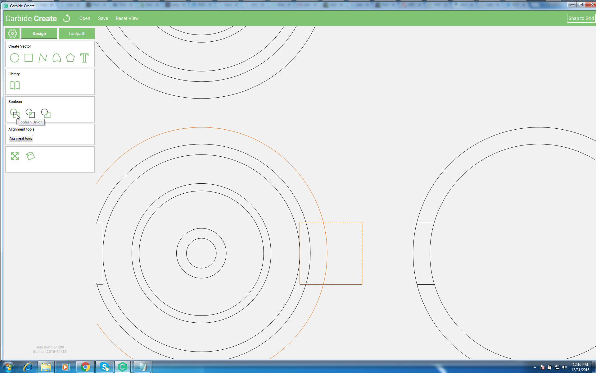
Basicly what you will want to do is create 2 Arch shapes.
These 2 arches dont meet in the middle, which leaves a tab.
What I did:
I made a Circle larger than the wheel by the diameter of my tool plus .01"
Then I made a rectangle to straddle the larger circle.
Then I used the boolean tool to cut the small and large circles.
The Trick to this is making multiple copies of your shapes and using the grid to snap them back into place as you cut the shapes with each other.
Ultimately a Thin skin will probably work just fine.
Thanks. I get as far as making the outer circle, square overlapping both circles, Boolean Subtract and I’m left with a circle with half a square indent. I’m close to understanding it.
Here: