EDIT to save reading the whole thread - The problem was solved by calibrating the steps per mm via the MDI (consult Carbide support for help with this).
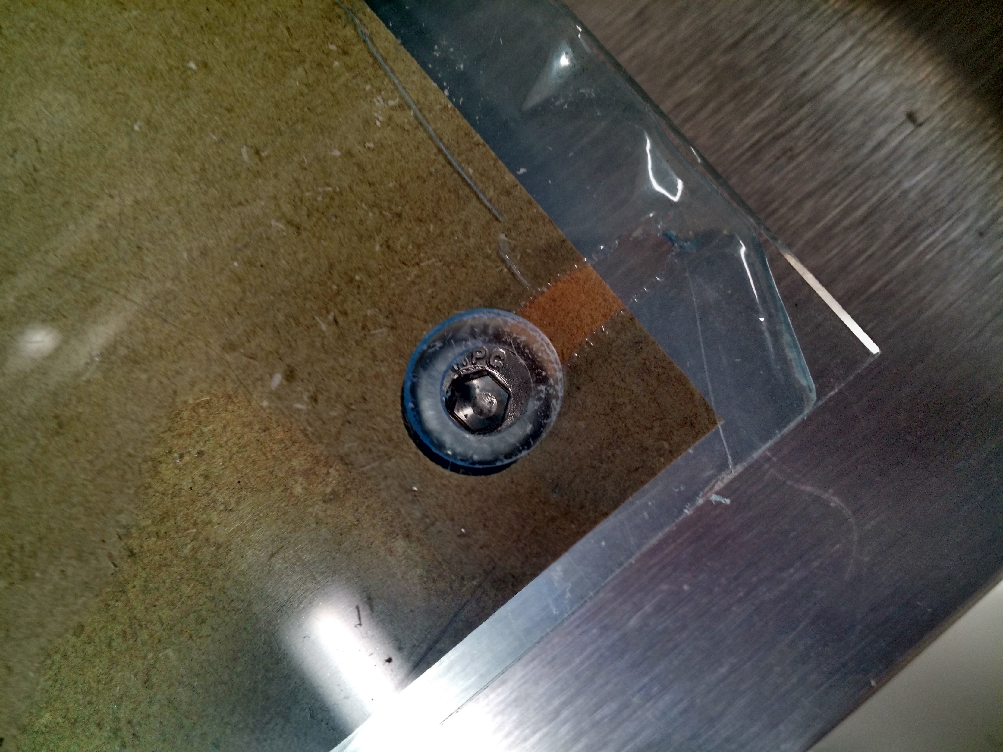
I was attempting to make a wasteboard/protector for my aluminum threaded table. However, when I cut the acrylic the distal holes were ~1mm out of alignment (see photo of the right hand hole)
The hole diagonal to the zero had the error in both the x and y axes.
I checked the file and the G-code (as best I could) and both suggested the mounting holes should be 7 inches (177.8mm) apart, yet they repeatedly were cut >7" apart. So far I have only made small items (clamps etc) so haven’t noticed any inaccuracies but I’m suprised the machine is so far out of calibration. I have read that calibration can be done via the MDI. Is this the next step or am I missing something obvious?
If Will’s info doesn’t solve your problem, feel free to post your code, as well as a sketch of your setup (which includes your home (X0Y0), and I’ll see if I can help.
I also see from your code that the part is not a square, it’s a trapezoid, which would explain the difference from the top holes to the bottom holes.
So before I look any further, is it suppose to be a Square OR a Trapezoid?
EDIT: I case I confused you: It looks like the holes were placed in from the right and left (side) edge, but since the part is not square, the distance BETWEEN centers are not equal (Top holes to bottom holes). I hope this helps.
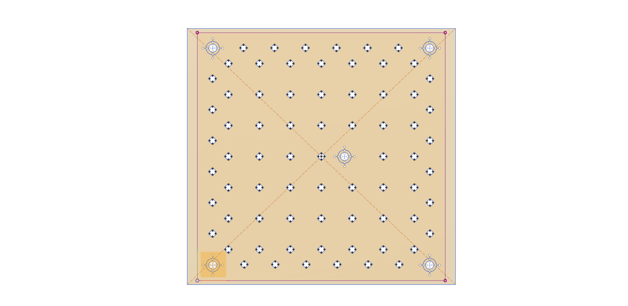
EDIT 2: From your photo of your part, it looks square, so perhaps you didn’t click on the hole center. Meaning it is very easy to click the hole edge, I should know I have done it several times. This is a problem with F360 (Notice from my attached photo that there is a small black space showing a difference from the top to the bottom: Look at the yellow square)
Thanks for your time on this. The red bounded square represents the threaded table (or waste board) this was created from an svg posted on the forum by will (dimensions should be square). X0Y0 is bottom left corner of the red square and set on the bottom left of the waste board on the machine. The external (non red) trapezoid represents the dimensions of my stock acrylic I created this from the centre of the square in fusion and the centre of the stock was aligned with the waste board centre…
The measurements to check the distance were made in the sketch view of fusion 360 from the hole centres.
But do you see what he is telling you there, Paul? That you made your selection the circle rather than the center of the circle, and that likely accounts for the error you’re seeing?
Thanks Rich and Phil I thought it maybe something stupid.
Just so I understand and can learn from this (sorry that you have had to explain multiple times). Do you mean that if you select the edge of a circle in fusion 360 for a pocket it is not keeping the tool inside this boundary?
Ps I scaled the svg so the dimensions matched the wasteboard/baseplate correctly. When I measure the sketch in fusion it displays 7" between the hole centres.
Some SVG and DXF files are what I call dirty. Rather than a polyline creating a circle, it is created out of 100’s (if not thousands) of points, and to F360 a point is a point. So either:
the file is wrong (either Scale or drawn incorrect) (sorry Will))
you didn’t zoom into a hole enough and might have clicked on an edge rather than the center.
I drew the part from scratch in fusion 360 (without using the SVG). The large holes are 7" apart; yet, when I tried to cut them, the same thing happened (they cut further apart).
In software I was measuring centre to centre. For the part I measured edge to edge.
I haven’t cut a slot that is the diameter of the tool (I thought this was bad practice generally). If it were a tool diameter issue, I would expect the pocket to be larger rather than just offset. Also the corner holes are offset by the same amount in either x or y (or both x and y for the diagonal), suggesting it is a scaling problem.