It’s a switchable power supply and the output is exactly the same sir.
I don’t see where you are setting your X0Y0 in the setup sketch (compared where you are actually setting the X0Y0.
Meaning computer (Model) and actual must be exactly the same
I also see from your code that the part is not a square, it’s a trapezoid, which would explain the difference from the top holes to the bottom holes.
So before I look any further, is it suppose to be a Square OR a Trapezoid?
EDIT: I case I confused you: It looks like the holes were placed in from the right and left (side) edge, but since the part is not square, the distance BETWEEN centers are not equal (Top holes to bottom holes). I hope this helps.
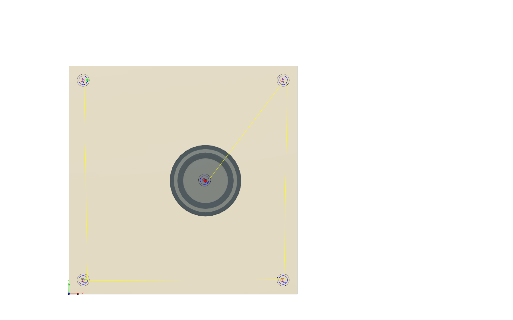
EDIT 2: From your photo of your part, it looks square, so perhaps you didn’t click on the hole center. Meaning it is very easy to click the hole edge, I should know I have done it several times. This is a problem with F360 (Notice from my attached photo that there is a small black space showing a difference from the top to the bottom: Look at the yellow square)

2 Likes
Hi rich
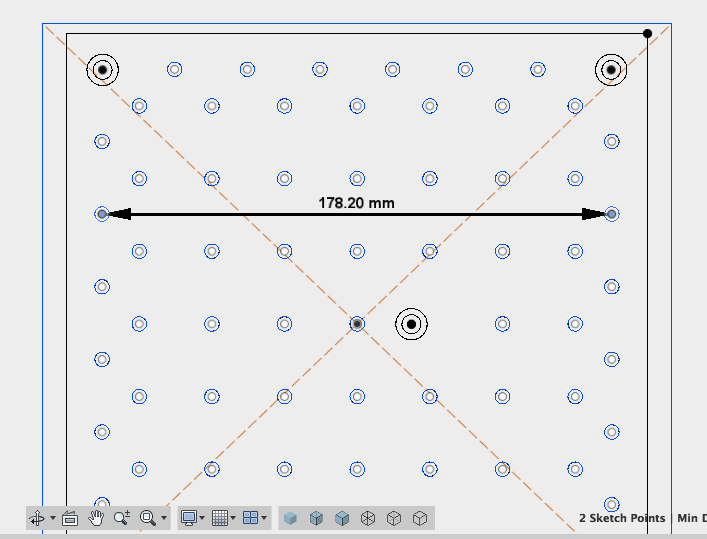
Thanks for your time on this. The red bounded square represents the threaded table (or waste board) this was created from an svg posted on the forum by will (dimensions should be square). X0Y0 is bottom left corner of the red square and set on the bottom left of the waste board on the machine. The external (non red) trapezoid represents the dimensions of my stock acrylic I created this from the centre of the square in fusion and the centre of the stock was aligned with the waste board centre…
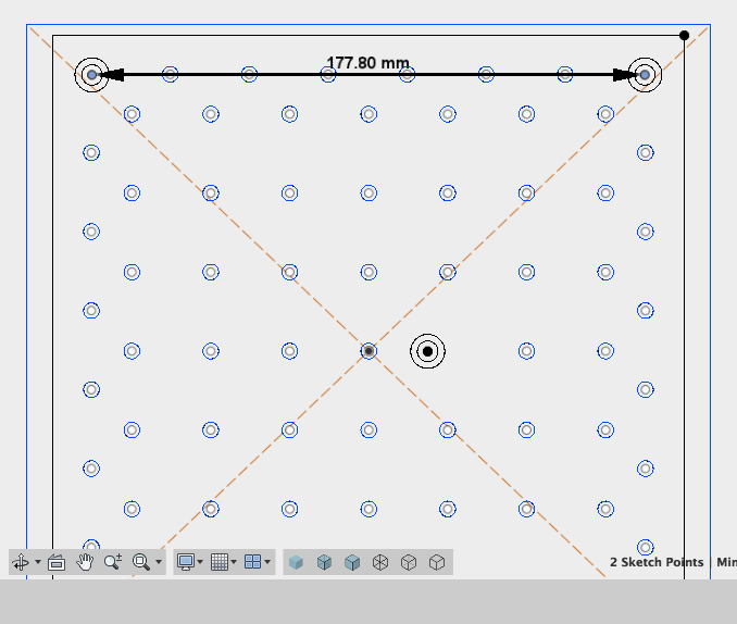
The measurements to check the distance were made in the sketch view of fusion 360 from the hole centres.
I hope this answers your questions
Thanks again
But do you see what he is telling you there, Paul? That you made your selection the circle rather than the center of the circle, and that likely accounts for the error you’re seeing?
Sorry, not sure what you mean.
When you say selection do you mean the contour of the pocket or for measuring the distances?
Distances were measured from hole centres.
To cut the 2D pocket I selected the circumference of the circle. Is this incorrect?
Let me try to say it another more direct way because you didn’t understand my previous post:
What I am telling you is the program is correct. It mills/drills you exactly where you told it.
Unfortunately, they are NOT where you want them.
Importing an SVG may need scaling in F360, and or it is not correct (or maybe both)
So it’s NOT the machine error, it is an operator (programming) error.
Thanks Rich and Phil I thought it maybe something stupid.
Just so I understand and can learn from this (sorry that you have had to explain multiple times). Do you mean that if you select the edge of a circle in fusion 360 for a pocket it is not keeping the tool inside this boundary?
Ps I scaled the svg so the dimensions matched the wasteboard/baseplate correctly. When I measure the sketch in fusion it displays 7" between the hole centres.
Some SVG and DXF files are what I call dirty. Rather than a polyline creating a circle, it is created out of 100’s (if not thousands) of points, and to F360 a point is a point. So either:
-
the file is wrong (either Scale or drawn incorrect) (sorry Will))
-
you didn’t zoom into a hole enough and might have clicked on an edge rather than the center.
That about covers it.
OK I’m confused again
I drew the part from scratch in fusion 360 (without using the SVG). The large holes are 7" apart; yet, when I tried to cut them, the same thing happened (they cut further apart).
Here is the zipped fusion file
nomad threaded wasteboard v1.zip (258.0 KB)
Any suggestions?
How are you measuring? center to center or edge to edge?
Have you cut a slot and measured it to get effective endmill diameter?
In software I was measuring centre to centre. For the part I measured edge to edge.
I haven’t cut a slot that is the diameter of the tool (I thought this was bad practice generally). If it were a tool diameter issue, I would expect the pocket to be larger rather than just offset. Also the corner holes are offset by the same amount in either x or y (or both x and y for the diagonal), suggesting it is a scaling problem.
The small holes are based off of Will’s drawing. I thought it was odd that the right hand column were not aligned to the others, (I plan to measure the threaded baseplate to see where they should be but I haven’t got to cutting those yet). I have only tried cutting the large holes that are 277.8mm (or 7") apart. Once I can cut those accurately, I’ll move on to the others.
My apologies then — it’s either an error on my part, or some incorrect translation from PDF to SVG to Carbide Create. Missed that it was my file you were using.
Obviously as a penance I have to re-create this thing in Carbide Create and do it accurately.
You did grab the files from:
No problem, It was a while ago I downloaded it, but I think that is the file I used. Once I have it working I’ll post a corrected fusion 360 version and an SVG in a separate post.
Paul,
OK I will disregard the 177.2 holes. Can you send me the latest GCode file for this Fusion 360 model?
PS It’s odd that the CAM side was empty (No work).
The original is here:
and I’ve update my post with a new version w/ drawn in bolt holes, rather than leaving the polylines from the tablet.pdf file in place.
Hi Rich, here is a simplified version (just the wasteboard dimensions and the large pockets)
and the g-code and fusion file
nomad cornerHoles v3.zip (98.7 KB)
Thanks once again
Update in case anyone runs into the same problem. The problem was solved by calibrating the steps per mm via the MDI (consult Carbide support for help with this).
1 Like