Inaccurate positioning

I am having an issue I haven’t seen before.

The key issue is locating holes for dowel pins to align a microscope stage. The spacing is specified as 70.000mm+/-0.050mm (3.00mm pins). This should be reasonable for the Nomad, though at the limit. With taper-lead dowel pins, it is likely to be good enough, as, over 70mm, the position should be within 0.029mm using the 0.005"/ft spec from the spec sheet.

Well, I have blown a day (5:30AM til now, 5PM) trying to figure out why the stage replacement won’t fit. The dowel pins won’t even start. Re-ran the job with only the locating holes. No fit. Maybe the bore operation was the problem, so I removed it and drilled at 1.5 mm and finished to size by hand using 3.0mm drill on the drill press. No go. Finally I got smart.

Drilled the pilot holes at 0.8mm, fit snug gauge pins, and actually measured. Center to center is 69.71mm. This is equivalent to 0.050"/ft (0.29mm/70mm–> 0.00414mm/mm, or inch/inch… 0.00414*12–>0.0497inch/ft). This is consistent whether the positioning is done as a pure X axis move or a pure Y axis move.

Is this due to the Gcode being generated in mm? I can’t imagine why it would be, but… Is there another issue?

Gcode generated using Inventor with HSM, redid the model with Fusion, checked the Gcode and the moves are correct. It is included below (with most of the Z moves for peck drilling removed) The machine is a Nomad Pro (feb2016, Ser no 127) using Carbide motion as the sender. I did not change the tool spec when I changed drills. Main reason I changed drills was because I needed a size for which I have matching gauge pins.

%
(1001)
(alignment holes for nikon scope)
(T2  D=1.5 CR=0 TAPER=90deg - ZMIN=-5 - drill)
G90
G17
G21
G28 G91 Z0
G90

(Drill1)
M9
T2 M6
S10000 M3
G54
M9
G0 X15 Y3
Z15
Z5
Z2
G1 Z-0.2 F30
G0 Z-0.1
(REPETATIVE PECK Z OPERATIONS REMOVED)
G1 Z-5 F30
G0 Z5
X85
Z2
G1 Z-0.2 F30
G0 Z-0.1
G1 Z-0.4 F30
(REPETATIVE Z PECKS REMOVED)
G0 Z-4.5
G1 Z-4.8 F30
G0 Z5
Z-2.8
G1 Z-5 F30
G0 Z5
Z15
M9
G28 G91 Z0
G28 X0 Y0
M30
%

So are you saying you got the right result in HSM, and the wrong result in another tool?

Is it the center-center distance that is off, or that the pins won’t go in the holes you think they should? Is there enough clearance in the hole for it to be a sliding fit?

Both tools same result. The Gcode is specifying the correct positioning (70mm travel between the hole centers) but the actual spacing is off by 0.5%. I ran several more tests today, including a grid on 10mm centers, and the error is uniform over the grid and consistent through several tests, though the X axis and the Y axis differ (which I did not realize yesterday) with the X axis being .5%, and the Y axis being about half that. On a 10mm grid, the spacing is a consistent 9.95mm (and 99.5mm +/- 0.02 over a 100mm span) for the X, and 9.98mm for the Y. Run X major or Y major doesn’t matter, so it is not backlash.

I am guessing that it is a controller issue in the Nomad, likely a configuration parameter, but I do not know how to set the calibration. If it was a belt driven machine, I would expect this,but on a leadscrew machine it is a surprise, and it is a small enough error I haven’t hit it in almost 1.5 years. This job requires dead on match for the alignment pins, and I would like to get there without having to bodge dimensions in the model if I can avoid it, both for this and for the future.

I also ran the same grid using inch units, and got the same result.

Huh. Did you upgrade to CM 4.0/GRBL 1.0? My understanding is that if you do this on a nomad (I haven’t to mine yet, I only did my SO3) that there are manufacturing time calibrations that are wiped out. That could account for a difference between what you used to get, and what you’re getting now.

This -can- be adjusted, but it seems weird that it’s suddenly off. You can do the same process as an SO3 calibrating for belt stretch (ie. $101, $102, $103 can be tweaked) and you wouldn’t have to massage the model. I’m a little cautious here though, because it’s strange that it changed. I’d recommend sending a note over to the Carbide support folks and getting their take on it.

1 Like

I haven’t done upgrades, as I have not had the need. I don’t think anything changed. This is the first thing I have done in 16 months that had to match an external standard cold. most of what I do is either all parts made on the machine or with looser tolerance. I have not had need to consider GRBL calibration settings, but may need to look there now.

I do not want to massage the model, as it may be (probably will be) used with other machines and/or as the basis for other parts. I have produced a few patterns for casting, and those models are built to actual size and a new model is produced at the appropriate shrinkage scale for generating the Gcode. That is enough of a headache to keep track of, and I do it by deriving the model rather than using the (buried in configuration and setup so it is easy to lose track of or forget about) scaling tools in Inventor or SolidWorks.

Any advice is appreciated here. One of the things I was interested in is if anyone else has had a similar issue. I would not expect it with the leadscrews in the Nomad, but things happen. I think my task tomorrow (today was 6+ hours on the phone with Verizon to initialize the new router they insisted I needed) may be mounting the mikrokator on the spindle carrier, an angle plate on the bed, and making some measurements with gauge blocks to see exactly what the X and Y axes are doing…

Check your Grbl steps / mm setting and write in to support — I suspect it’s a just barely in spec lead screw, so adjusting steps / mm is the thing to do — should be harmless to test, so long as one notes the original values.

The one concern I have is for the tool length probe… suggest deferring on Z until checking in w/ support.

The issue is resolved, I think. Long description of what measurements I took and what the parameter changes were for anyone that may be in a similar situation at any point. Digital cameras are nice, as I was able to take a shot of each measurement to reduce the risk of misreading. I will tack a couple samples to show the setups onto the post later if anyone cares.

Having nothing better to do today (that I wanted to do), I spent way too much time quantifying the travel for all three axes. I would put more weight into the results if I had done this when I got the machine, before the wear in the leadscrews, but I found interesting results.

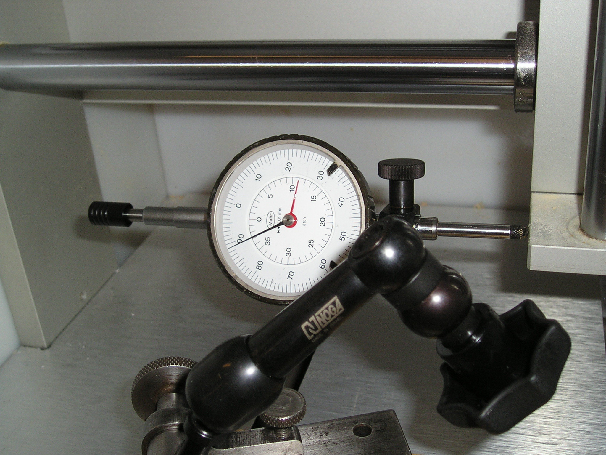
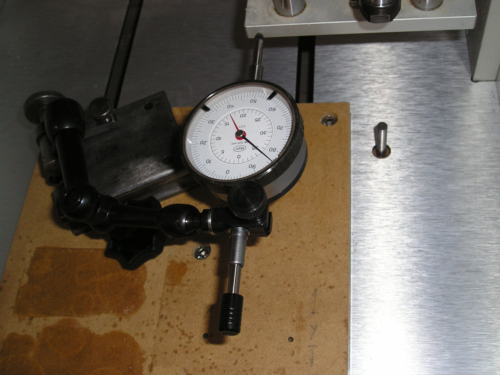
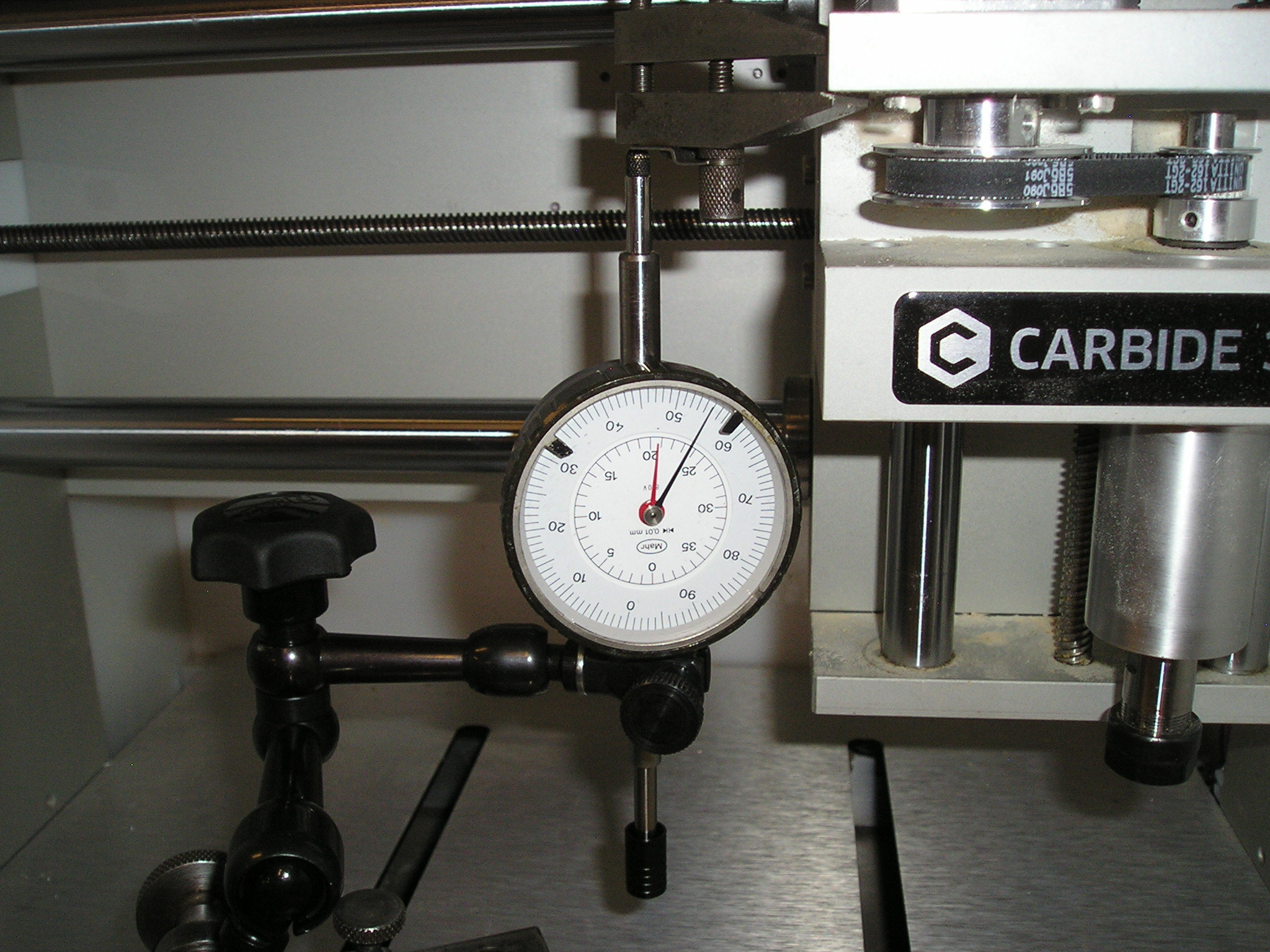
The equipment was a heavy surface gauge base, Noga arm, and Mahr 810 (near) constant force 40mm travel (0.01mm resolution, 0.003mm repeatability, 0.025mm max error over range, recently certified). The surface gauge was located on the bed by boring holes for the drop pins into the waste board and using spray adhesive (scotch super 77) to tie it down. About as rigid as it can get without boring and threading the bedplate for the indicator mount. I would have used the 125mm indicator (ya, I got some special measuring tools) for the X and Y axes so I could quantify from a single central reference position, except that it isn’t in certification, and I would have needed to remove the cover as it is nearly 500mm long.

Alignment was referenced using the X and the Y guide rods, and was good enough that the indicator tip did not shift laterally during the measurements (close enough not to exceed the play in the spindle bushings for the indicator). It is about the end of the season where I can control the temp and humidity of the workspace, so I was at 23C, close enough to 20 not to need compensation. It is supposed to get hot and humid over the weekend, so that may take me out of range for some measurements until the fall.

Fired up PuTTY for communication with the controller, wrote down the original variable values, and went to town collecting data.

What I found was that the X axis leadscrew travel is (using factory setting of 200.0steps/mm) fairly uniformly 0.0047mm/mm low, with little variation over the entire length. This was measures by making 5mm travels to 35mm (to reduce risk of crashing the 40mm dial indicator) and recording the actual position relative to the starting point. Then, reposition the indicator for the next 35mm and do it again. And again. And again… Each segment was reversed in the same 5mm increments as a check, and the measurements matched within the measuring instrument spec throughout, indicating insignificant backlash in the leadscrew.

Since the X axis error was pretty much uniform over the screw and repeatable, I reset the steps/mm variable and reran the test. The error is now well within spec. I reran my gauge piece (the 70mm spaced holes) and the hole centers came in at 70.05mm, well within tolerance.

I did the same for the Y and Z axes. I figured the Z axis would have pretty significant non-uniform wear, and was not surprised. I was surprised by the Y axis, until I though about how I usually set up jobs. about 80mm of the leadscrew is all over the place (+/-0.05mm or more per 5mm travel), but the rest was a uniform 0.03mm/10mm as the X axis, so I reset the steps/mm to match and know where I have the highest accuracy. The Z axis was all over in the area that get the most use. I took a bunch of measurements (5mm increments), did some stats, and reset the Z axis as well.

Overall, not a major issue, and manageable. Just took time. I only ran a small segment of the X at 0.05mm increments (for 5mm) to look for cyclical errors. I didn’t note any that weren’t within the spec of the measuring tool (0.006mm hysteresis), so by Ockhams Razor will assume a lead error on the X axis screw, but not drunken threads. It is still as good (or better) than the leadscrews on some of the (new) manual mills I have used.

To get the new value for the steps/mm settings, I used (1-discrepancy)*current

For the X, the discrepency was -0.0047 (0.16 to 0.17mm short over 35mm) and the original steps/mm value was 200.000, so 1.0047*200.000–> 200.940 steps/mm.

Retesting gave about 0.01mm error over the 35mm travel, which is essentially nil (half of that is taken up by uncertainty in the measuring tool, and all of it is taken up by two of the nominal 0.005mm step of the machine) and well within spec for the machine. The Y and Z came in better than they were, as well, but due to the uneven wear, they are compromises. This does tell me that at some point in the future, I am investing in replacement leadscrews. Probably be a few years, though. It is no where near the limit yet.

All in all, an interesting endevour, and I have the first fixture I need done. The 70.00mm center-center came in at 70.05mm (+/-0.02 using a 50-75mm Mitutoyo micrometer), which is in tolerance, and, even better, allowed the dowel pins to slide right in to the microscope alignment holes. Figure a 0.01 or 0.02 runout and/or wander at the tool, and that would give this much error. Now, on to the other fixtures for the same microscope.

3 Likes

A few pics of the setup for measurement

X axis setup

y axis setup

z axis setup. I used a toolmakers clamp to oget the dial indicator away from the spindle carriage

3 Likes