I am getting minor indentions along the X axis when surfacing stock. It happens in the same spot X axis no matter the location in Y or Z. This likely happens on all jobs but is really noticeable on aluminum or the like. It’s like there is a flat spot in one of the V-wheels making the Z change ever so slightly. Depth of cut and feed rate don’t play a role. Any thoughts?
Maybe loosen your X axis belt from one end (so the stepper is disengaged), roll the carriage around and inspect for any binding in the movement? Could also try rotating the V wheels a bit by hand and see if the blemish moves? Maybe even rotate the tires like you would a car, move the tops to the bottoms, bottoms to tops? To me this looks pretty obviously mechanical, so I’d do just like I would any other mechanical device try different things and see if the problem a) stays the same, b) changes to a different area, or c) corrects itself after the change is made. One thing I learned long ago as a mechanic is to change ONE thing at a time while troubleshooting, test, repeat, till the culprit is found, otherwise you’ll never know what fixed what…or if you induced some other problem with the change, and what caused it.
You were a bit ambiguous on the initial post. I believe people though you were getting an indentation in your X rail
What you mean is your getting marks along the stock when traveling X. This means your spindle needs squaring - some people use shims under the top or bottom of the spindle mount.
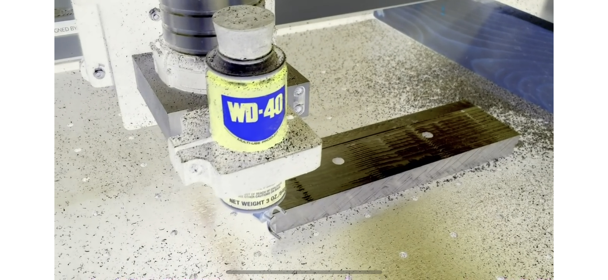
Sorry I thought it was clear that the attached photo was a stock of aluminum.
Ridging would mean that the spindle isn’t square, right? My issue is that at certain parts of the X axis, there is a minor variation in surface finish. Some probably 3/8” in length. Others down to a 1/16th maybe? This leads me to believe that it’s something with the V wheels themselves.
For example, a flat spot on one of the top X wheels would tilt the spindle ever so slightly that direction causing the minor variation in angle being cut repeatedly along the Y axis like I am experiencing.
If it was the spindle alignment itself, wouldn’t it look the same over the entire surface area of the stock?
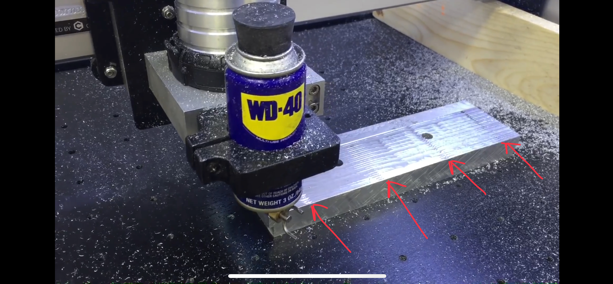
I am getting the same effect as the screen shot posted of one of Richard’s projects. And I’m sure that we can say with confidence that his spindle is square.
This is so minor that it is only evident on a surface finish like aluminum. If you’re cutting wood and plastic, you’d never know that this was happening. But on aluminum, it sticks out like a sore thumb and I’m wanting to leave the parts unfinished.
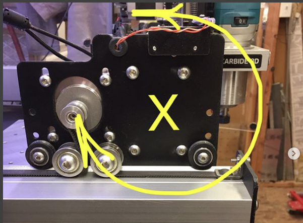
interference from the flanged bearings used as idlers
imperfections along the belt
slight imperfection along the V-rail of the extrusion
I would start by flipping the X-axis belt end-for-end — change one thing at a time and see which affect this in what way. It’s a really subtle thing, difficult to measure.
Take a card from a deck of playing cards, and try to slide it between the steel flanged bearings, and the aluminum extrusion. If you can’t fit the card, or if you see that the wheels have caused any gouging in the extrusion, then you need to adjust those wheels/axels “up” and then adjust your belt tension.
PS: I “used” to get these lines. Note the age of the video. Old Z Motor plate and before I squared up my spindle (and fixed the bearing that was rubbing on the X-axis rail).
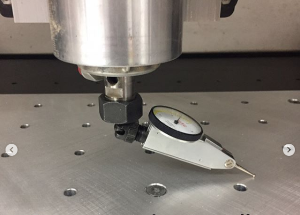
First, let’s comment on your spindle arriving squared up. It was not. (PS The spindle will go out of square during use, this is normal for ANY machine, and needs to be checked every 3-6 months depending on the type of work you do)
Proof: Primarily since you installed the X axis rail onto the Y axis motor plates. (See Photo below and now please go watch @wmoy video on squaring the machine, but please purchase a test indicator rather than using his spacer technique to fix your machine.
I never said it arrives squared. Far from! I had to shave out some holes to get it rotated forward along the X-axis. Just re-squared just last week actually in preparation for my upcoming aluminum projects