Thank you for the purchase! We hope your machine will work out well.
The machine can do inlays, but it’s a bit challenging getting the files ready for the machine to do this. Let’s take a look at some of the options in broad strokes:
-
software (specialized or general done manually) — there are a number of commercial apps for this, some quite sophisticated, or amazingly capable (esp. the one which is a plug-in for Adobe Illustrator). Some of the free/opensource software also has this feature
-
nature of the inlay — there are a couple of options here: square endmill and vertical sides and solid materials, V-bit and angled sides and solid materials, square or V-bit carved pocket which is then filled with something — one can do an offset cut using a V-bit which will fit and that avoids many of the complexities of using a round bit as described below.
We’ll work through how to handle this with the default software and a round endmill — let us know if you have any questions!
First, draw or find a suitable vector file, e.g., File:Flag of Canada.svg - Wikipedia
Then, open it in some suitable tool — we will first try to directly open it in Carbide Create.
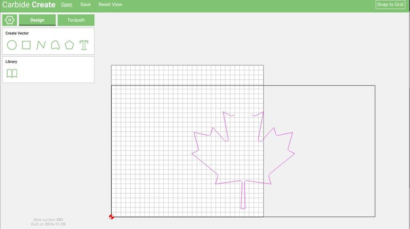
Although unplanned, for didactic purposes, this would have been hard to beat. The image is incompleat, so we will need to examine it in some other tool and fix it — we’ll use Inkscape.
If necessary, download and install Inkscape from http://www.inkscape.org then open the file in it.
To see how the file is truly structured, switch view modes: View | Display Mode | Outline:
Select everything to determine how the file is composed — a layering of:
- path (the maple leaf)
- rectangle (the white square
- rectangle (the flag itself which is masked out in the center to yield the two rectangles to either side)
Ideally, we would instead want: path (the maple leaf), as part of a composite path with the white square (each having suitable path directions), two separate rectangles for the red panels to either side, and an overall rectangle to define the overall dimensions.
To arrive at this, we will need to:
- zoom in
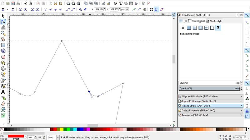
- select the “Edit Paths by Nodes” tool
- click on the Maple leaf to select it
- click on one of the two nodes which defines the gap by not being connected to the other
- Click on the “Draw Bezier Curves and Straight Lines” tool
- click on the selected node
- click on the other node to fix and close the path
Zoom out, select the Maple leaf and the square and select Path | Difference to get the desired composite path:
We note that the square is positioned at 250 units in from the left edge of the page, and that the square itself is 500 units wide. This then makes it straight-forward to:
- select the rectangle
- Edit | Duplicate
- change the width to 250
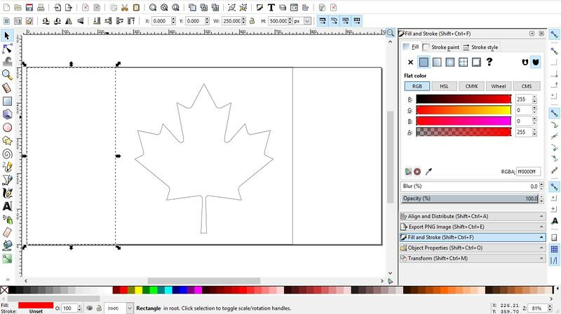
- Edit | Duplicate
- change the X position to 750
The graphic should now be ready to save to a file and import into Carbide Create.
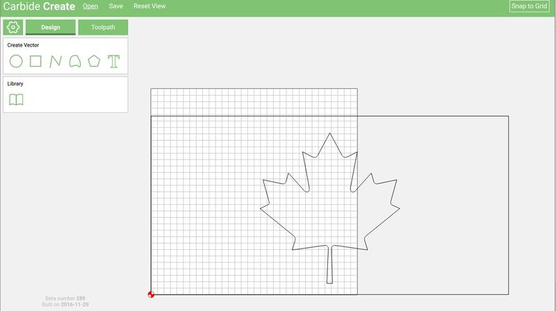
The SVG import filter for Carbide Create seems to delete redundant geometry — but since we know the proportions of the flag, this is simple enough to fix within Carbide Create:
- click on the outer rectangle to select it, note the dimensions
- gear icon
- set the stock size to match the dimensions of the rectangle
- click to deselect, then click again to select to load the Design pane for this object
- select the bottom left corner as the origin
- set X and Y to 0 and click “Apply”
The balance of this should be obvious w/ Apollo’s notes below — let us know if you have any questions.