Please see attached results. Prior to running the test I have squared the frame by loosening / tightening rail screws method described in the wiki. The front of both Y plates contact the front frame. If anything the left Y plate wants to have a few thou gap but I held it against the front frame when I powered the motors and it stayed. The X extrusion is shimmed to square it to the Y carriages and Y extrusions shimmed to square them to the front and back frames. Spindle is trammed and wasteboard flattened. Belt stretch was calibrated. I used 1/4” flat endmill #201 at 0.1” doc and 54 ipm in 3/4” MDF. It’s really hard to measure corner to corner of the Y extrusions but front left to back right may be 1/32” longer than the other way. What steps do you guys recommend I take next to improve the squareness? Thanks!
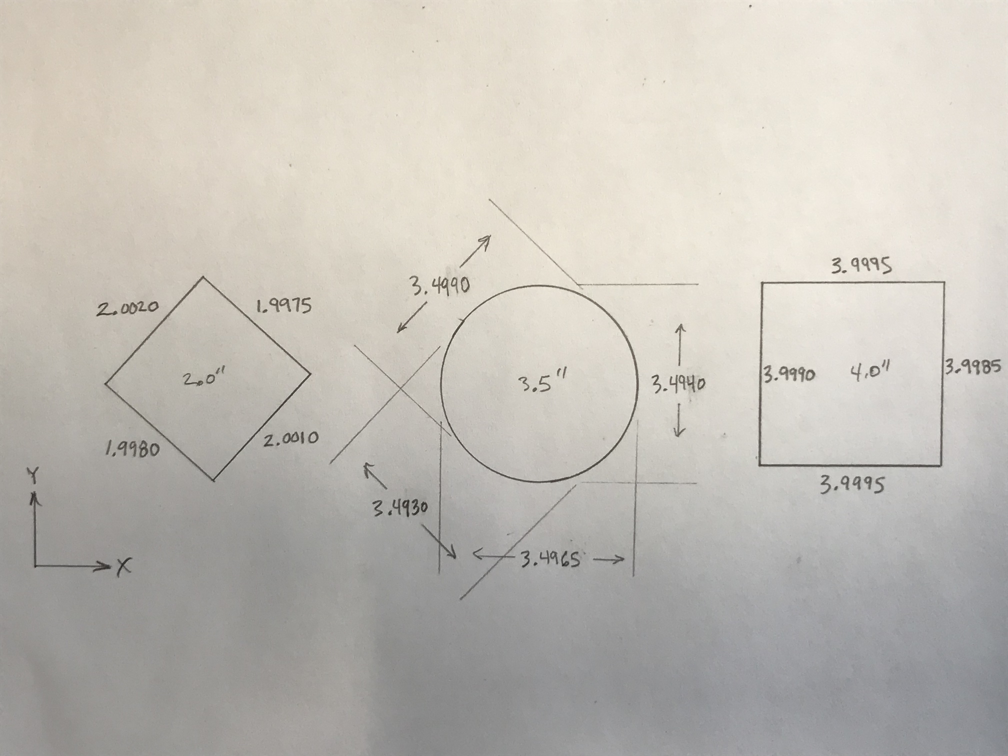
I’m confused by the circle falling short along the same angle that the diamond is long, and am curious what the NE–SW diagonal would measure on the circle.
Did you leave a roughing clearance and take a finishing pass here? I’m wondering if the endmill is getting pulled into the cut along some dimensions — looks quite good though!
I thought the same thing about the circle coming up smaller. I think it’s because the calipers are measuring “point to point” on the circle, and a little pressure may create a flat spot on the MDF. For the diamond and square the calipers are making flat surface contact and less likely to compress the MDF/more surface to pick up the high peaks of the surface. NE-SW measurement is shown.
I did not have a finishing pass… just the standard pocket cuts in CC. I actually used the CC file provided on the wiki.
Can you recommend what I can do next to improve the squareness? I’ve read through all of the links I could find on squareness but didn’t see much about making small calculated tweaks to it.
I was thinking that if the back frame is skewed to the right resulting out of square of 0.001” per inch… I could shim the front right side and back left side of each Y extrusion by a calculated amount to bring it back? Of course would need to to loosen up the wasteboard before that. Thoughts?
Thanks
Jeff
At this point, it can be a maddening, tail-chasing circular thing, of diminishing returns, but hopefully continual improvement.
I believe one should start from large to small and work your way inward — but before doing that, I’d really suggest working up a better calibration blank in a less yielding / more stable material and doing a cut which has a roughing clearance and takes a finishing pass — hopefully you’ll be surprised.
Might this be a basic signal to noise issue?
Although the calipers display measurements in 0.0005" increments, it does not mean you are measuring things that accurately. When I use calipers it is because I want to measure something +/- 0.001". To get a better measurement one needs to use a better tool.
To overcome the potential error in your measuring I would use as large a calibration pattern as my machine and measuring device allow.
What is your goal here?
Everything I read says that for the Shapeoko you should expect +/- 0.003" - 0.005" in terms of accuracy. It looks to me like you are there.
What are you trying to make that requires more accuracy than the machine is advertised to produce?
Ok I’ll try a couple more CDS with hardwood and finishing passes first. For finishing pass in CC… offset the shapes by 10% of 1/4” cutter dia and do normal pockets, then follow up with outside line tool paths at full DOC for the original shapes?
Yes, that’s I believe the best way to approach it — it’s at least a good / valid approach.
Good points. Yes I agree the 4th digit isn’t very useful. I will say that I took each of those measurements multiple times and checked back to zero each time and the calipers are not the cheap kind and are calibrated. I also machined a 12” inside corner (a supplemental fence) and it was out .011” over 10.5” in the same direction (measured with machinists square and feeler gages). So the same trend exits on a larger scale. Maybe I’ll try an 11” CDS.
My goal is to get it as good as I can with a reasonable effort. I’m close but so far there is a pattern.
Jeff
If it’s that consistent, then I’d be inclined to go with a lozenge shape / out-of-squareness to the machine since you’ve got the circle oddity explained.
One thought — uneven Y-axis belt tension? Try drilling a set of holes on each side of the work area long the Y-axis — if they’re different, then adjust Y-axis tension on the looser side?
I need to make some more before I can say it’s that consistent. 2 for 2 so far though. Lozenge- That’s where I was going with the talk about shimming between Y axis rails and front/back frames.
I’ll try your suggestion about the Y axis belt tension too. Hopefully I can make some chips tonight.
Thanks.
I cut some slots along each Y-axis with a nominal distance of 11.25”. The left side measures 11.247” and the right side 11.250”. So the left Y-axis is a little slower than the right. At 0.0003” per inch, I guess that means it is not the major factor though.
First correct your steps per inch to achieve a 4” x 4” square on each side. It does not need to be perfectly square, but each side needs to be 4” parallel from the other side. If you can’t get a perfect square, run two grooves 4” apart in each axis to calibrate your steps. This is critical prior to moving on to the CDS.
You need to measure corner to corner of the square to lead you in the right direction of what needs to be corrected.
The difference between corner to corner divided by 2 divided by side measurements ( either 2” or 4 “) will give you the amount per inch you will need to correct corner to corner on the machine. If you have a std SO3, multiply result by 26 or XL or XXL by 40. You can also use a dial indicator against the gantry to move the X gantry in either direction the amount of error you need to correct( result of calculation x inches away from Y rail). You will need to have your steppers energized to use the dial indicator method.
This does require patience. Take your time and have a few adult beverages if required.
I forgot what I set them at last time… Is there a way to figure out what the current steps per inch are set at? Or if I have a new factor of 1.001… can I do $100 = $100*1.001 ??
Hey Craig, can you explain your math for calculating the amount per inch needed to correct corner to corner? I don’t follow.
Also using your measurements, I’m out .000625” per inch * 40” = 0.0025”. It is long in the SW-NE direction. Can you explain the dial indicator method in a little more detail, and where I need to make the adjustment?
I did 3 consecutive CDS in pine today and got very consistent measurements.
What do you think about shimming the front right and back left side of each Y axis by a trig calculated amount?
Thanks!
You can get your current settings by opening a Log window and sending $$ to the machine.
Grbl won’t do math for you — it’s far too memory constrained for anything along those lines.
I believe that shimming or machining the extrusions is the next logical step.
Give me a few days and I’ll try to make something presentable.
If you have time watch William Ng’s ‘5 Cuts to a Perfect Crosscut Sled’ on YouTube. It is effectively doing the same thing except we are not adding error from 4 cuts to determine the machine error, we are using the known variance from a ‘square’ cut with the machine and measuring corner to corner to determine the amount of error and converting that to determine how much the machine is out of square corner to corner so we can determine the tangible amount of movement we need to adjust the frame to get within desired tolerance. A perfectly square square will measure equidistant corner to corner.
@WillAdams is it me or is the belt calibration formula in this doc wrong?
The written text is right, but the formula is backwards…
Jeff
Let’s see:
We have a machine which should be set to 40 steps per mm, which is instead set to 80 steps.
We tell it to move 1 inch, but since it moves 80 steps where it ought to take 40, it only moves 2 inches.
2 ÷ 1 == 2 * 80 == 160
which is backwards
So instead it ought to be:
1 (desired movement) ÷ 2 (actual movement) == 0.5 (ratio) * 80 == 40
so
75mm (desired movement) ÷ 75.03mm (actual movement) = 0.999600159936026 (ratio) × 40 (current steps) = 39.9840064This topic was automatically closed 30 days after the last reply. New replies are no longer allowed.