I also found this on my Nomad, though I had the right side higher than the left. I ended up milling the waste board flat level by taking a quarter mm off the board each run until the whole board was level with the tool. There may be an adjustment of the bed somewhere or a software calibration method that needs to be done so as not to waste the waste board.
You two are on the right track - there are two variables at play here, and without some prior exposure to CNC, it would be hard to guess what they are let alone make plans to correct them.
The bed itself is a fixed piece of the machine that has no adjustment. We’ll want to leave that alone.
Variable #1 - Uneven wasteboard. This is an easy fix, and @zmocar came up with the correct answer: You need to surface the wasteboard so it is true to your spindle. Taking 1mm off the entire board (assuming the lowest point isn’t more than 1mm) will achieve the desired results. You may even be able to begin by taking 0.5mm away. This is a common thing that needs to be done on all CNC machines. You don’t need to do it all the time, but anytime you install a new wasteboard, OR your wasteboard becomes too scarred up, you’ll need to run a surfacing operation.
Variable #2 - Uneven material. Chances are really good that the material you are cutting isn’t perfectly flat. In fact, if you took a reading across the material you will probably find at least a couple thou of difference from one side to the other. You have two choices
1.) If the material is something you’re engraving (i.e. you want to save the top of the piece)- you can figure out a way to shim it (from the bottom) so it’s even. This isn’t all the common of a practice, but in some cases can be done. Or, you can flip the material over and surface the face you’re not concerned about keeping.
2.) Just like in Variable #1, you can surface the material you’re going to be cutting from. Standard practice would be to use a material that’s slightly thicker than your design calls for. After you’ve loaded the design into meshcam, you can set the ‘extra’ material to be on top of the z. Then, by default, meshcam will mill that material away before it begins cutting your actual design.
-Edward
2 Likes
I’m needing to revisit this topic, previously I concluded the waste board was not level but after using the new Carbide 3D vice (and not getting level cuts) I decided to measure the base/bed metal plate.
http://coldcoffee.club/wp-content/uploads/2015/04/z-heights-base.png
Below are my measurements from 13 points. The difference between the lowest (measured) point and the highest (measured) point was just over 2mm (2.05). I attempted to use colors to show the difference, but in case that doesn’t work the basic description is that the upper left corner is high, and the lower right corner is low.
http://coldcoffee.club/wp-content/uploads/2015/04/z-heights.png
The Nomad 883 is my first CNC machine so I’m left wondering if this is normal? If any of you have the time could you please measure your base plate and tell me your results. It took me about 20 minutes (in Carbide Motion) to move to the 13 points and measure the Z axis.
FYI: I used Carbide Motion version 2.0.314 (2015-04-10). The new quick positioning made this somewhat easy.
Have you checked the bolts that hold down the table? Maybe they are not torqued down evenly. Just a thought - but maybe you should remove the bolts, check and clean the mating surfaces on the table and machine, then then reinstall ensuring you torque each bolt down evenly - go around and do opposite corners and then the middle, a little more torque each time till they are tight.
Something is not right there. We pay extra for the MIC-6 aluminum that we make the table from because it’s the flattest stock material we can get. Generally, if we put a piece of it on a granite table then we get it sticking to the table slightly because it’s so flat.
Can you tell me if the gap varies from the bottom of the table to the Dibond cover underneath it? There’s only something like 1-1.5mm of clearance so if one side was low by 1 mm then I would expect it to be visible.
What serial number is your machine?
-Rob
1 Like
The short answer is “it depends”. If I move the base towards the back of the Nomad (so the spindle is over the bottom edge) there is a noticeable gap difference (first photo).
http://coldcoffee.club/wp-content/uploads/2015/04/z-height-base-back.png
However if I move the base towards the front of the Nomad (so the spindle is over the top edge) there is not a noticeable gap (second photo).
http://coldcoffee.club/wp-content/uploads/2015/04/z-height-base-front.png
Serial number is 102
Can you shoot an email to support@ to create a ticket. We think it’s due to a missing washer under the table.
-Rob
Carbide 3D took care of everything. It was indeed the washer(s) under the table. Very happy with the result and what a positive experience to have the owners of the company respond so fast and personally walk us through the fix.
ColdCoffee - I had a similar experience. The z axis motor on my machine started going nutty, and Jorge diagnosed the problem within a few minutes (a wire had somehow got damaged leading to the motor)
He sent me a new wiring harness express, and I just installed it - and the machine is back up and running! Awesome service from the Carbide3d folks 
Same here, Jorge helped me too troubleshoot a problem I was having, and now all is working fine. First class service from them!
Always happy to help! We want all our Nomads out there cranking awesome stuff 
Hi all- I would like to level my MDF wasteboard. Can someone please post a protocol using meshcam and Nomad #201 (or other tool). thanks -Peter
Where is this option in Meshcam?
My stock will be slightly out by maybe a 1mm, so I was thinking of milling a 8 mm part using 10 - 11 mm stock would this work?
Tim
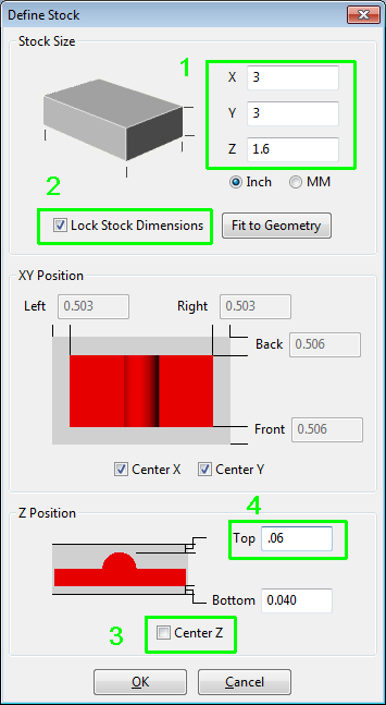
Tim, in the Define Stock dialog do this:
-
Define the stock size and
-
Lock the dimensions
-
MeshCAM’s default behavior is to center the geometry in the stock so unselect Center Z
-
Edit the top or bottom margin. The other one will update automatically because both the stock thickness and geometry thickness are fixed. (If you do not lock the stock dimension MeshCAM will monkey with the stock dimensions as you edit the margins).
Randy
1 Like
Hi Randy,
Bit confused, on Z Position what is 0.6 and 0.040 for?
Tim
Tim, on my example the geometry is 1.500" tall (I see I didn’t actually say that, sorry). I used samplerhino.stl. I defined the stock to be 1.600" tall just so there was some wiggle room. So the sum of the top and bottom stock margins is (1.600-1.500) = 0.100". For my example I specified a top margin of 0.060", so with the stock size locked the bottom margin works out to 0.040". What you are really doing is positioning a fixed stock around your fixed geometry.
The other way to go would be to load your geometry, leave the stock size unlocked, enter your desired margins, and MeshCAM would tell you how big the stock must be to give those margins. Then you’d cut a piece of stock to that size.
But in my experience it’s always much easier to square up the stock and measure it, than to try to square it up and size to a predetermined dimension at the same time.
Randy
1 Like
Thanks Randy for the extra explanation
You’re welcome, Tim. But it is not so much “extra” explanation as much as “bringing up to adequacy” of explanation. 
Randy
1 Like
Did you do these measurements with a cutting tool in the collet or some kind of probe? Thinking I may need to do the same check on mine after noticing some things in the low-profile vise coming out a bit oddly (but consistently oddly with one end higher than the other…)