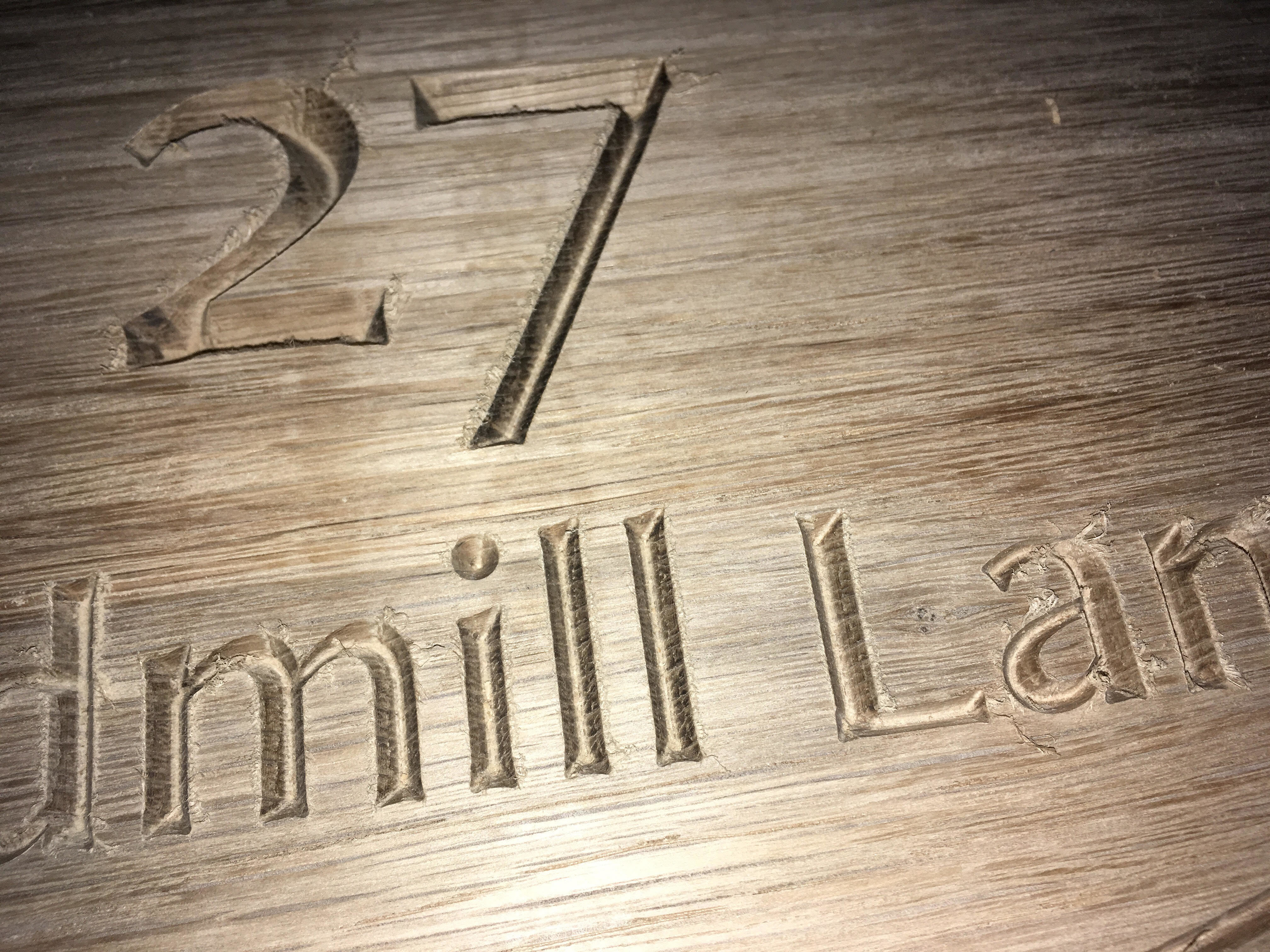
Hi guys, I’ve just attempted my first engraving on oak and I’m getting this odd result shown in the picture. I’m using a 60 degree laser point 3FL CMT Orange tools bit and I made the engraving file in fusion 360. All the edges should be crisp and straight. I put the tip for the engraving bit in as 0mm as it’s very sharp. The text is about an inch and a half tall.
You’re talking the little dog-bone wiggles at the corners? Assuming you’re machine is mechanically sound either you’ve got a slightly-off angle’d vbit (50 vs 60 degrees), or your zeroing is slightly off.
Thanks for the reply Adam - could that be my Z zeroing? I got it as good as I could get it using a piece of paper to feel for when it started to make contact. Could it potentially be my feed rate? I cut this at about 500MM/M and it didn’t seem to chatter, but I was just guessing as I’ve been finding it difficult to find a reference point.
20ipm (~500mm/m) doesn’t sound too wild, assuming this isn’t a super super tiny bit of work.
Yep, Z axis zero’ing. Paper work ok, but I’m a big fan of feeler gauges - Get a .005" (or any small one, really) and slide it under the point while dropping it by .001" until it just starts to drag the gauge. Then pull the gauge, drop by the gauge’s thickness and you should be about as accurate as can be had.
Played around with the heights but unfortunately I get the same result… I have a 45 degree bit which works fine, but all of the 3 60 degree bits I have give me funky results. I’ve obviously changed the angle in fusion to 30 for the 60 degree bits, since it seems to be the angle per side, but I can’t get around these results. I tried the V-Carve option in carbide create but I get the same results again… very odd.
I checked my pulleys, belts and v wheels earlier… with the exception of the belt holder on the Z plate - will have to have a look at this. The only other thing I can think of is that I adjusted my steps/mm a week ago (before I ever tried V-carving) to get them perfect. I actually ended up bringing the X and Y motors down to around 39.87 if I remember correctly, but bumped the Z motor up to 40.5 I think - could this account for this kind of error in the cut?
With the 90 degree Trend router bit I have, the cuts are MUCH cleaner, making me think it’s not an issue with the mechanics of my machine, but a software/technical error. However, with the 90 degree bit, the cuts are less deep, involving the Z axis less and leaving less room for error - right?
Could be that a reduced z travel results in a lessened effect, I’d have to ponder that one
Try swapping your steps/mm back to the stocks and see if it helps. I went through and did the same for mine a while back and technically got “more accurate” but I swear the results were the same or worse than the stock settings.
Oak especially white oak has some particular grain patterns due to its open pores that can result in some odd tear out situations.
My suggestion is to cut the pattern the initial time with your setup. After it finishes, without changing anything, cut it a second time. VCarving can sometimes be a fickle thing and the second pass will clean it up if you are cutting too fast or the router is spinning too fast. Make sure your router is at it’s lowest speed if using the Dewalt and you have not modified it with lower speed control. My guess is you are running the router at too high a rotational speed but dont know for sure
If the above doesnt work, I would then try it in a different wood that is harder. Like maple, cherry, ash. These woods are not nearly as prone to tearout and tend to cut much cleaner when vcarving.
Let us know if you get it working better. Always good to know what works for troubleshooting for us all.
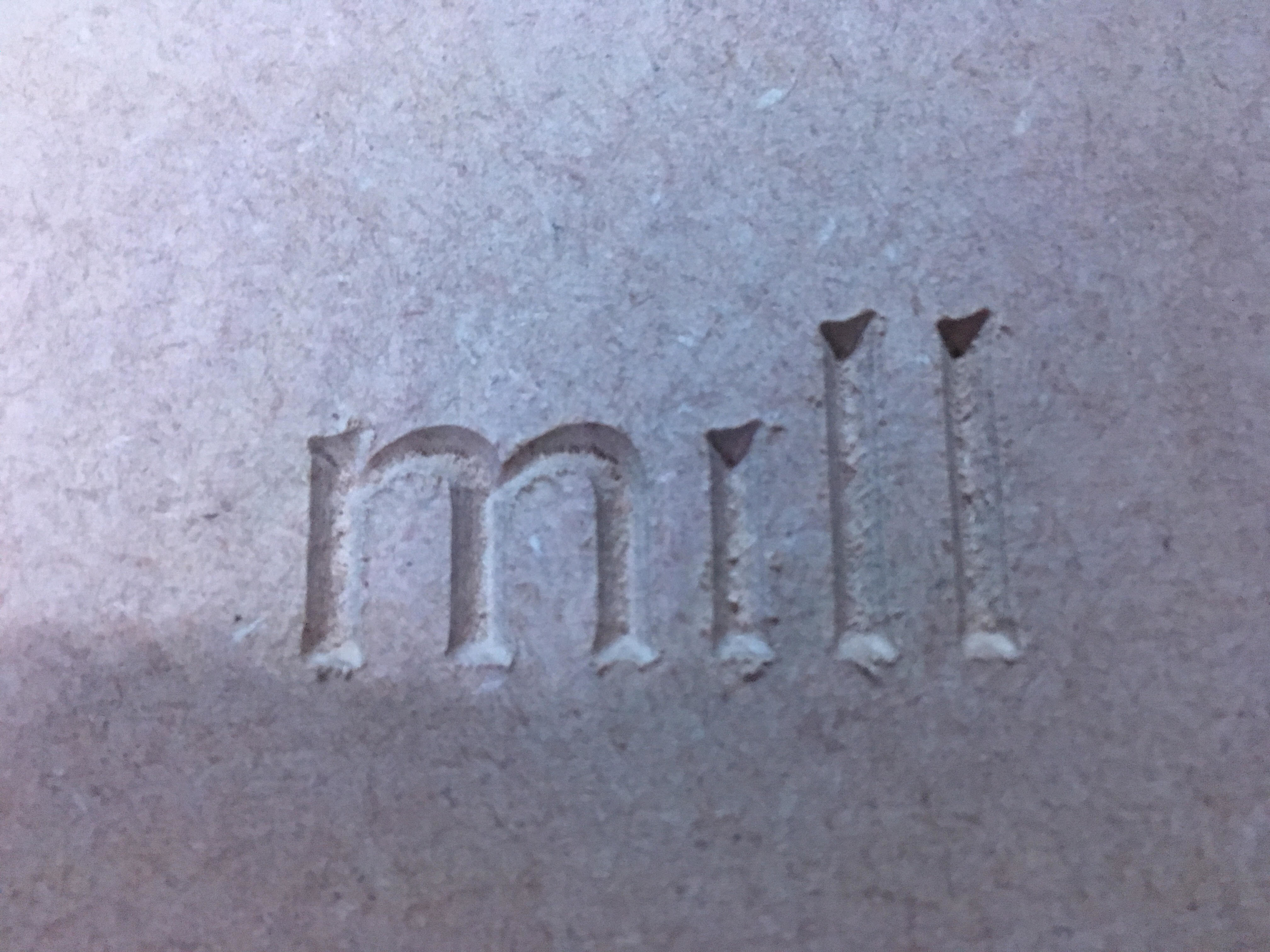
Thanks for your replies Stacy and Adam. Here’s a cut made in MDF with the same bit and the same settings in Fusion. I changed my steps/MM back to 40 but nothing seems to have significantly changed unfortunately. If I do the same cut with the 90 degree bit, everything looks great. (With the bit angle set to 45 degrees in Fusion)
I suspect your endmill isn’t actually the angle which it ought to be or the software is getting the calculation wrong.
First, try different software to see if generating the toolpaths w/ a different tool fixes it — if so, contact Autodesk.
If not, then make up a test file w/ several different labeled triangles each of which is set to be cut w/ a V-bit one degree less or more acute than the one before it, then cut w/ this endmill and see which one comes out accurately.
I dont use fusion but in Aspire, there is a difference in a V-bit and an engraving bit. A 90 degree v-bit setup as a v-bit would be 90 degrees. The same bit setup in the engraving bit would be setup as a 45 degree bit. Check to make sure you have the bit setup correctly. I think the engraving bit is specified as an included angle and not the total angle It gets pretty confusing and then add flt tip bits into the mix and you end up with ultimate confusion.
I was looking for a 90 degee v-bit with a .03 inch flat last night and only found one company that even supplied them.
Yep, full depth as I can’t see any other option within Fusion, however I also used Carbide Create and had the same results - not sure if Carbide uses several passes by default?
Just noticed that one of the set screws for one of my Y axis motors isn’t aligned perfectly over the flat - does anyone have any tips for getting the pulley off the motor as I don’t want to use too much force and damage it!
I don’t think it’s slipping as I haven’t had any issues with cutting regular shapes with good accuracy, but I’d like to make sure.
Take out the two set screws and it should turn without any problem to allow you to align it. My best advice is to install some grub screws with larger heads instead of the small set screws. I replaced all the screws in my machine and it is much better. You can get a little more tightness out of the screw and blue loctite them. I havent had one move since.
Hi Stacy, thanks for your advice - I’ll get hold of some bigger grub screws. I’ve removed the set screws however the pulley refuses to turn independently of the motor - mine’s a recent machine so it came preassembled with what looks like red loctite on the shaft - any tips? I don’t want to start hammering away at it because I know that can damage motors!
You can get a small motor pulley at Harbor Freight or an automotive store that pulls on the wheel sides while pushing on the shaft pin. They are pretty cheap.
As Will said, this really sounds like a calculation error. In vectric’s software, their vcarveing operations a vbits use the full angle of the bit (60 or 90 in your case). Are you specifying a flat or start depth with your vcarve paths?
Like Will said, your bit probably isn’t a true 60 degree. You can change the angle to 29.5 or 30.5 etc. etc. in the software to bring it back into to tolerance.