So, really, one would have to exclude V-bits or touching “between” flutes to find XY zero?
Correct. V bits can only be used in probing the Z-axis.
Forgive my ignorance, but this is kind of what I’m thinking about with a touch block. If the Z height doesn’t change and one is using a touch block with a hole in it for XY, why would it matter what shape the bit is as long as it is symmetrical and you touch the cutting edges? Your software is only subtracting the absolute coordinates to find the chord length.
You’d need to probe for Z first, and the angle of the V would need to be consistent with the provided specification, and not all the V endmills are consistently shaped due to flutes and so forth — the measurement would vary based on which way the endmill was rotated.
Would this description be the same for the Carbide3d touch probe, too. Would touching the outside edges be any different?
Yes, but that’s why probing in X and Y isn’t done for V endmills.
I just solved that problem.
I turned my endmill into a cylinder while trying to mill aluminum. Perfect probe! (doesn’t seem to cut the way I hoped, though)
Back on thread topic, I’d love to see some toolpaths by those experienced in cutting aluminum.
1 Like
I sent Ed a message through Instagram about maybe having a little contest. A cool design that anyone could try out of wood or metal.
He was all about it and was willing to put up some cutters or a maintenance kit up for prizes.
Now I’m not sure how to get everyone involved or even what type of design.
Also gimme files and I’ll cam, gonna be up all night running an evo headflange anyway lol
@neilferreri, haha, I have some of those too.
Precise Bits sells calibration blanks, I think just what you need.
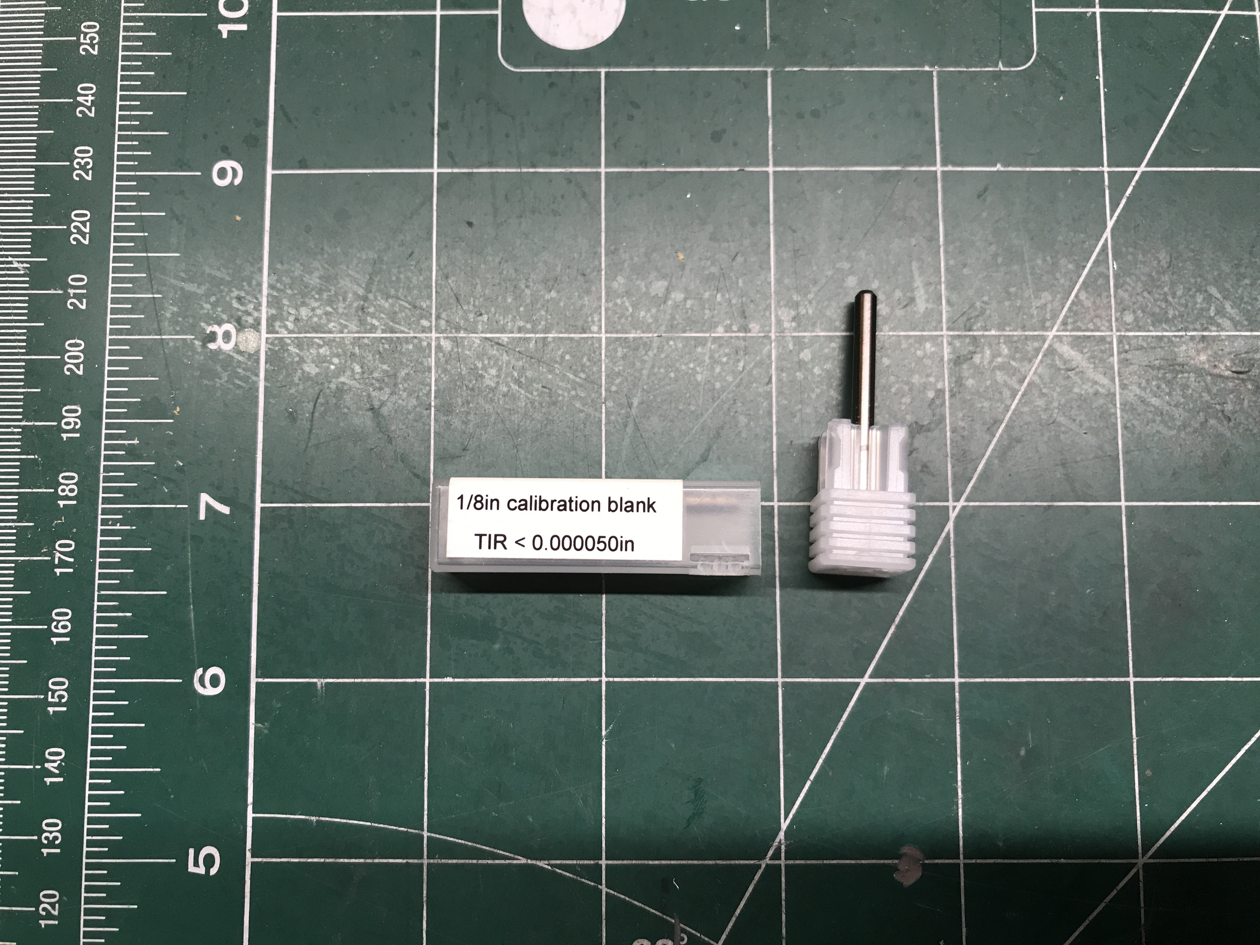
https://www.precisebits.com/index.php?route=product/search&search=Cb000
4 Likes
Here’s my first try.
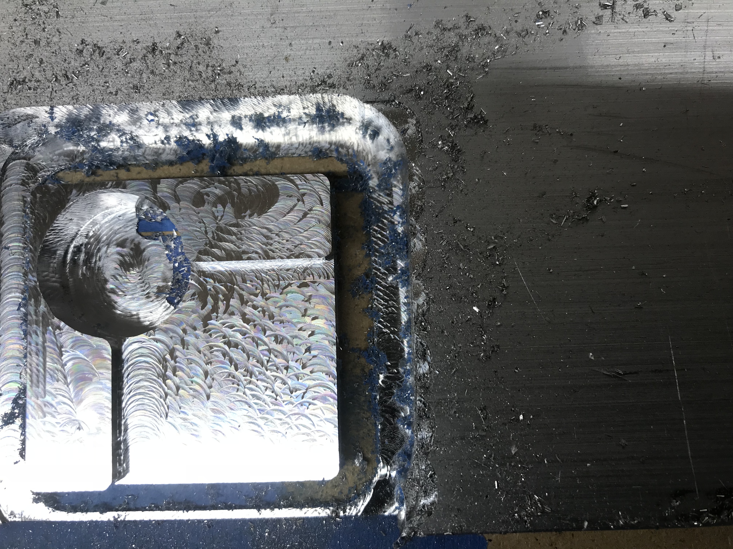
I’m going to use what I learned and cut another. I can tell you I doubled the cutting feed rate to 2000 mm/min, left doc at 1 mm. Both numbers can be improved further I’m sure. I also bumped the Makita up to 6. Started at 1 but saw some chatter when passing over the left edge into air, stopped when speed increased to 4. I will also cut my next stock to match your dimensions.
When all’s good I’ll share files
I’ve been messing with my router mount so…still need to finish tramming. Parts a little rough.
1 Like
@Griff
Awesome! Was that using the CAM settings I had or did you generate your own toolpaths? I tried and lost XY after the first, circular part of the adaptive path. I originally started with a depth of 3mm, but I reduced to 2mm with a smaller load (looked a little better), and settled on 1mm but haven’t cut. How are you keeping things cool and keeping the chips clear?
By the way, I had a sheet of 0.5" that I was using too. that’s why I tried using the adaptive toolpath to cut the profile. I’m here, participating, because I don’t know if that’s the best way.
@neilferreri yes your settings
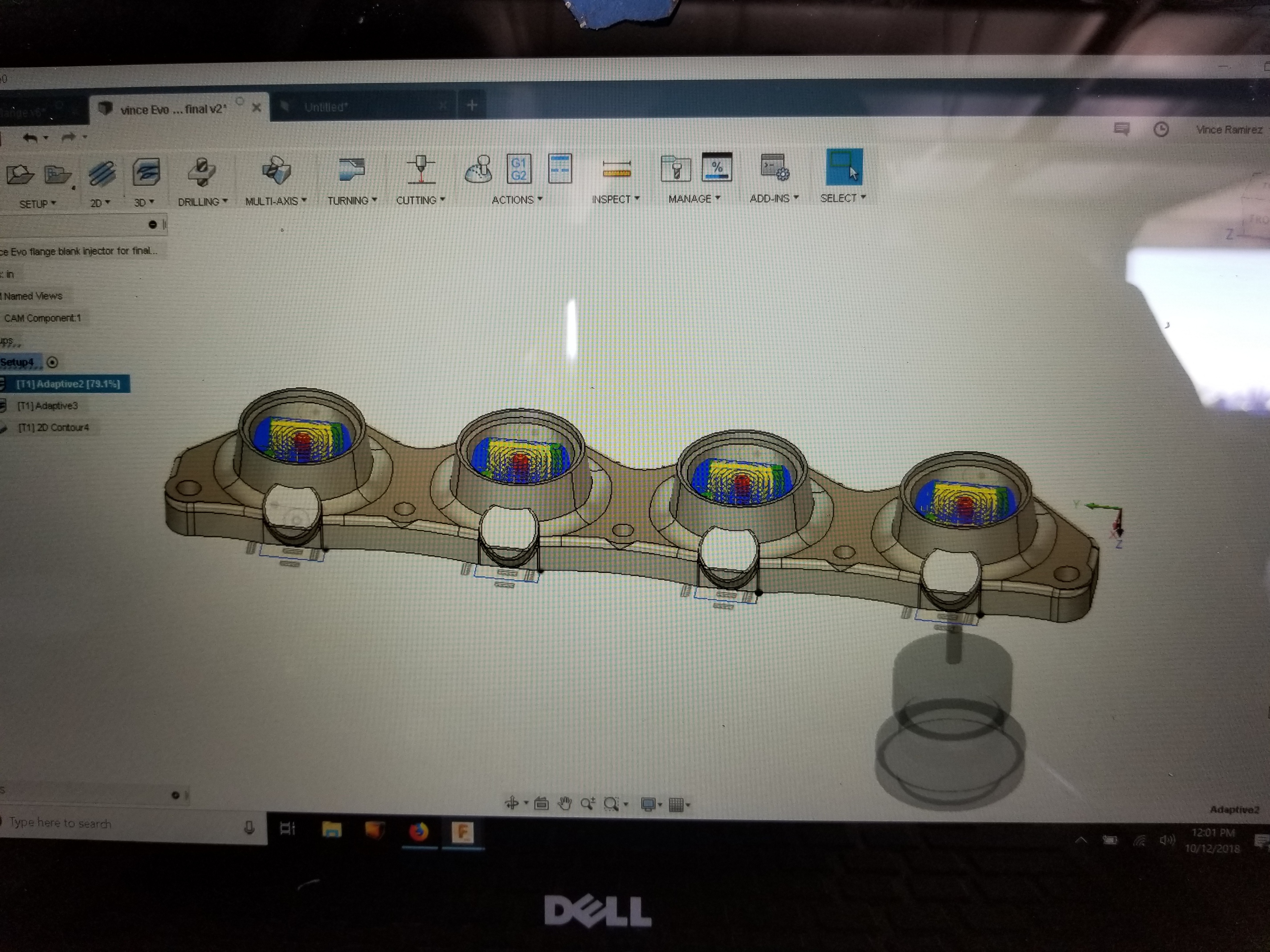
I used face 1 and adaptive 1. I modded the second adaptive for rest machining when I experienced the 10 mm max roughing step down, ahhhhhhhh! Nothing broke, no skipped steps, just a big dig into the probe hole taking a gouge out of the side.
You might like this:
As to the efficacy of this toolpath strategy, no clue. This is all learning for me. I’m going to guess that adaptive is good for the interior cuts and that a multi step 2D contour would be best for cutting the part out.
Stay tuned…
1 Like
Yikes…I’m pretty much winging it. I thought I had Adaptive two on rest machining, though. My thought was that I’d clear almost everything with a conventional milling in Adaptive 1, and come back with an almost full depth for the last 0.5mm with a climb cut. I wonder why it took a chunk out.
Again, I’m winging it and I’ve changed the settings a bunch of times. I love that you’re giving it a go!
I also have an old, unsure of the brand, mill that was in a closet at a different school. I took it apart, reassembled and got it running on grbl. The old controller was a PC running DOS. That’s where the other CAM setup is from.
I’m winging it too…My guess on the chunk is that the cutter dropped the full 10 mm into the hole then impacted the wall at 2500 mm/min engaging 10 mm of cutter 0.5 mm doc in an instant with the sidewall, not a good thing. I should have checked the toolpath better, that’s all.
You had stock to leave in the first adaptive at 0.5 radial and axial. So, 0.5 mm on sidewalls and bottom. It might be ok to remove that at 3 mm doc but not 10. I hope this makes sense.
I just finished another block using all 2D paths. Finish is not as nice plus I had to slow WAY down and reduce doc to .5 mm to complete the final contour cut to free the part. So, I’ll continue to mess with your basic setup and paths.
Yup. I’ve done full depth before, but probably not at .5mm. Here’s one I ran successfully for an earlier design. It wasn’t a great finish, but no catastrophes. I had some difficulty getting it to do what I wanted. When I have time, I’ll compare my toolpaths and find what I like / understand about each.
3 axis hole probe
tools used
250 tas rougher
250 2 flute variable
1" insert face mill
Pretty efficient cam but first time using the horizontal toolpath. I suspect homing cycle will mess with the finish if you are on stock limit switches. Setup and stock changed to be held with a vise, flipped, then Probe Top roughed/faced.
All surfaces roughed and finished. Please change feeds and speeds to your machines happy place.
Also adaptive is not a good finishing toolpath, I believe Saunders has some good vids on this
3 Likes
Pro tip - you can go from cam back to model and create a sketch, then you can easily create shapes for clickable boundaries in cam
This really helped me with isolating complex geometry
1 Like
I do tiling this way in Fusion too.
1 Like
Ide love to share my toolpaths but can’t risk others having the production files. How did you like my cam on the probe @neilferreri?
I might try to machine one out while the flange is running today
@Vince.Fab. Okay, thanks for the Toolpaths, VERY helpful to me.
I reduced stock thickness to 12.8 mm, x and y to 65 mm, model at bottom of stock.
I ran all paths as you set them up, all with the same .25 endmill, at reduced speeds/feeds, doc.
Initial speed at 2000 mm/min, bumped to 2500, DOC 1.5 mm, spindle at 28000, cheapo .25 two flute, non coated Carbide end mill.
As you might have guessed I skipped the flip paths.
This is a great part to learn on, thanks @neilferreri. I hope one of you smart guys will be kind enough to share some other, more challenging 3D designs and paths!
Oh, who is Saunders? Link?
2 Likes