How about provisions for mounting a jtech laser setup?
Morning Brian
I had thought about this - assuming you have a laser, can you send me some pictures on how you attach it now.
Update I have just added support for 1.5 and 2.2kw spindle mounts
1 Like
Well… I don’t have a laser.  so no can do on the pictures. It I wouldn’t mind one in the future. Along with a 2.2kw spindle…
Some people 
I thought about this allot. The best place to mount it in my eyes would be on the front of the spindle. But I can’t add holes for that easily… Unless you send me your bracket 
At least you can mount the 2.2kw spindle
I have a j-tech laser. But I haven’t mounted it on my new Z yet. Will share when I do so.
It will be some sort of removable setup. I had it permently mounted on my stock Z for awhile but had focus/lens-falling-off issues due to vibration when using the router.
Just need to source a few connectors.
Yeh? I thought magnets would be a good way to go…
I have a really good idea what would work for all shapeoko users. But I need some measurements from you.
One thought here — it’s my understanding that at least one of the mounts which Inventables offers has a set of drilled and tapped holes on it for mounting accessories — might be worth matching that.
Mini update. After thinking things through a little more and bouncing some ideas of @bborden there is a potential solution for suckit users.
I’m going to create holes on the rear of my X/Y plate for a plate to attach to.
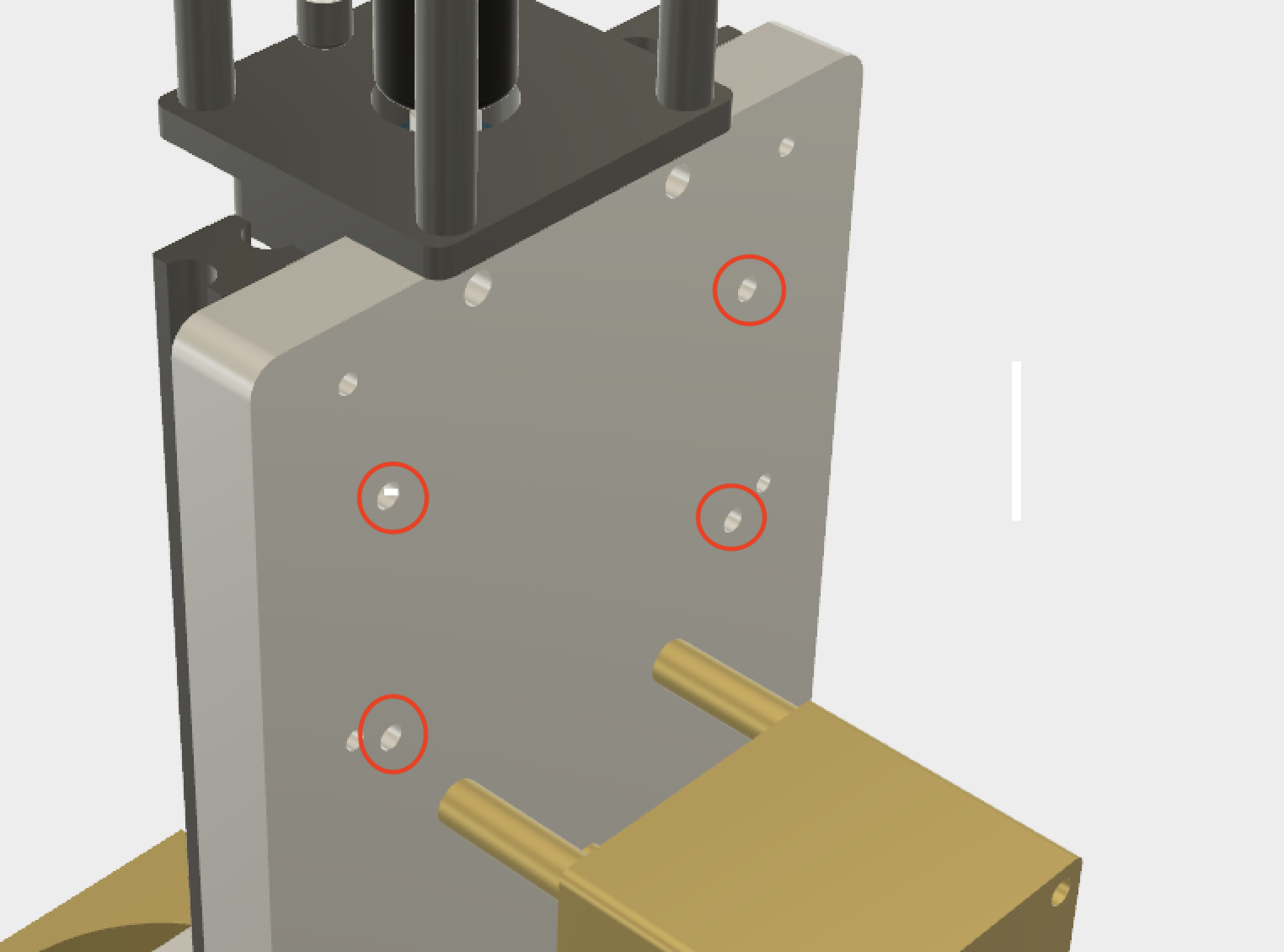
From this plate spacers would be added.
This will allow the suckit top mounts to attach to my design from the sides. I have reached out to the guys at suckit to see if we could collaborate on a solution. If anyone knows the suckit guys well I’d be keen for a introduction.
If you don’t have any luck getting longer arms made, i was able to get my Suckit to work by using some spacers between the arm and the plate.This brought everyhing out about an inch -

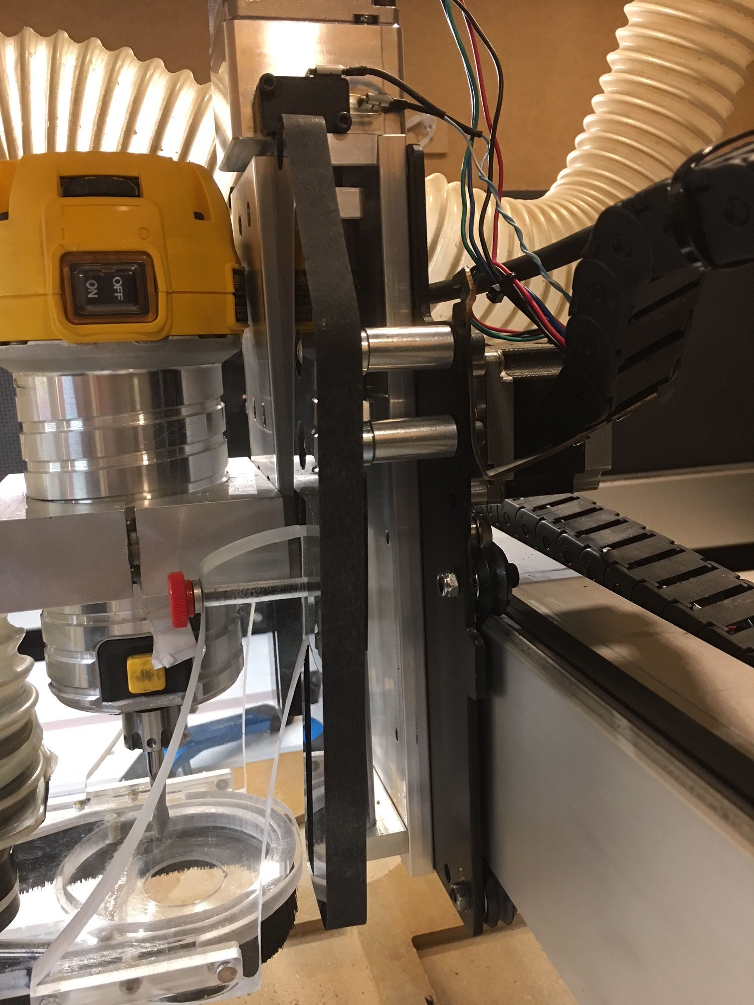
Even after using the spacers the base of the shoe was still about a little short. So I removed the magnets, slide the base out to where it needed to be, then glued it rather than using the existing screw holes. I can still remove the base, and now it aligns properly.
Not a perfect solution, but it works and I have not had to purchase any new parts. So if Luke provides mounting holes, you may be able to get your existing arms to work, I guess it will just depend on how much further it needs to stick out on his new slider vs the extending I had to do for my Z slider.
4 Likes
Good morning all
I’ve made some more minor enhancements.
I have also moved things forward, requests for deposits and an update email went out this morning.
If you want to get in on the first batch and have not had an email please let me know.
Future orders will be done through my new website
6 Likes
WoW Luke congratulations very nice space !. And the product shop very very nice too !.
2 Likes
I didn’t get an email this morning.
As a small update - I’ve brought things forward again. We’re now in the hands of suppliers.
I’ve just spend about £5000 on parts/deposits and sent the files through to my machining partner.
The only thing I haven’t bought is the thousands of M5 screws I need
Very exciting!
1 Like
Does the design require using your existing router mounts or are you machining new brackets etc?
Hi Eirik
It uses your existing spindle mount but it includes my special tram adjuster that should make tramming a breeze.
If you use a larger spindle it can also accommodate a 2.2kw spindle - and I’m looking to offer milled versions of these brackets.
Luke
Well leave it to Beaver, not taking the role of Eddie Hasker here, but this newbie owner os an S3 is clueless as to what either of these options does, who they are suited for, and just what is it about them which adds value to the existing device?
My wish list for C3D Create and motion is for them to add more basic features making it more Inkscape like. A measuring tool, a means to copy an object from an existing file then paste it into an entirely new file. A means to align type to a curve or to a shape, a way to create “macros” such as a box where all one need to do is supply the dimension info and voila, all sides, ends, top and bottom are created and positioned on the stock ready to be cut. Finger joints would be great but I see the built-in error factor of the bit radius at each corner. I’ve no idea what the brain trust in Torrence, CA is working on, but there is no shortage of seemingly easy software additions which would add great value. Nice hardware, not so impressive software. If I’d only known at the time. Sure you can do this and that. They neglected to add if you use other software. Not your day to keep them either but surely someone there reads the community traffic. Hope to learn more about your efforts.
Bob aka Beachbob
Hi Bob
There are a number of reasons you might want to consider a Z/X upgrade. I would say it’s not designed for a beginner - more of something to upgrade over time if you feel you need it. There are many Shapeoko owners who will find the standard setup suitable for there needs.
Here are some reasons you might want to upgrade at some point:
- The stock Z/X does have quite a bit of flex in it. This does it’s most to minimise it - granted it still uses V wheels on the X but they do have a tighter tollerance.
- The stock Z can get blocked and or jam - this one can’t.
- The stock Z/X can skip steps or slip - it’s allot less likely this will do either.
- It allows for a larger spindle i.e. 2.2kw - with little or no chance of slip.
- It has a higher plunging force.
- It offers a great height on the Z.
Best
Luke
1 Like
Hi @Luke ,
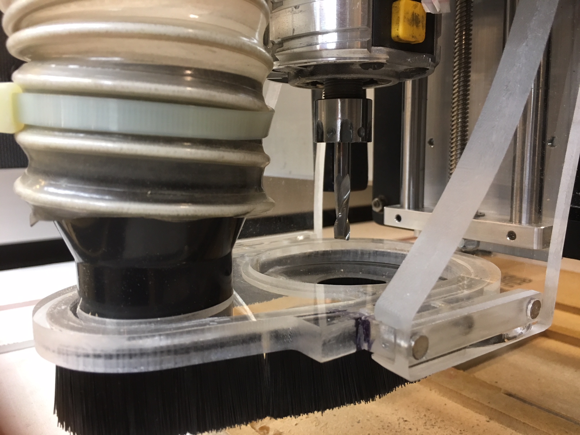
Happened upon this thread and am interested, however I see that you are reusing (or potentially rebuilding) the S03 spindle mount. The least rigid travel direction is in Y, which I believe is due to the V-wheels on both the X and Z axes being loaded perpendicular to the rail, but also due to the relatively large moment on the spindle mount, which has a very small load bearing footprint. I experience significant chatter when cutting deep passes in the Y travel direction, which is the limiting factor for feedrate on my machine. At the same speed, cutting in X is very smooth.
I ask this because it seems that you’ve done a ton of work to improve rigidity of this carriage replacement, but (to my eyes) are leaving the “easy rigidity” on the table and limiting the usefulness of the rest of the system by not replacing the spindle mount with a design that incorporates two rings to better resist the moment on the spindle. I have to imagine this will be compounded by the addition of the tramming mount, which will concentrate that moment onto the adjustment screws and the thin plate they are housed in.