Hey folks,
So I just did some two sided milling on my Nomad and the parts didn’t quite come out right in terms of the two sides aligning in Y (they aligned perfectly in X). This surprised me a little given that I had positioned the stock on two dowel pins oriented in a line perpendicular to the X axis along the center of the C3D sea of holes. I was using the center quick position in CM 4.12 for the milling origin.
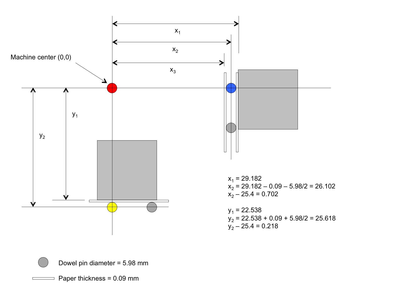
It then occurred to me that the sea of holes plate may not be precisely registered with the machine’s plate, or that the stored center coordiinates may not necessarily be calibrated with the latter. So, having a probe, I investigated, as shown in the attached image.
I placed two dowel pins in the holes one inch below the center of the sea of holes (closer to the front of the table), put my probe on a piece of paper to insulate it from the sea of holes and put a small strip of paper between the pins and the probe and zeroed Y there. (See the yellow dot on the attached image.)
Then I put two dowel pins in the holes one inch to the right of the center, put the same piece of paper next to the pin, and then placed the probe and zeroed the X there. (See the blue dot.)
I then moved to the pre-programmed center of the table and checked the offsets from the new zeros.
The drawing I’ve attached isn’t to scale, but the distance from the center of each dowel pin to the center of the table should be exactly one inch (25.4 mm). My calculations, shown on the drawing, show that the sea of holes center differs from the pre-programmed center by 0.702 mm horizontally, and 0.218 mm in Y. I should be able to use those measurements to get better precision on two-sided machining, though I haven’t yet tried it, by moving to the center quick position, jogging by the indicated amounts, then zeroing X and Y.
Anyway, just thought I’d share (and I’d give other analytical minds who lurk here a chance to double-check my reasoning and math).
Ah yes! I actually commented in that thread–your work probably planted the seed that eventually got me doing it without remembering your post. Having done it myself now, I’ll reread your thread with new interest and deeper appreciation!
@patofoto has a method of centering that is probably more precise than using the probe multiple times, and it is linked above. However, it requires a threaded center locating punch, and the table I have has metric threads–unfortunately, McMaster doesn’t have metric threaded center locating punches (at least, I didn’t see them).
So here is an alternate method (for Nomad), similar to my first one shown above, but simpler I think, and with the final setting of values in EEPROM as per @patofoto 's method. I’ve put it into a spreadsheet so that it can do the necessary calculations for you (but always double-check them yourself), and so that it can be downloaded and kept handy. Apologies for formatting differences between Win and MacOS…
For this project you will need:
• a probe with indicator LED
• two dowel pins that fit your sea of holes (measure diameter)
• small sheet of paper
• narrow strip of paper (measure thickness)
• tool or dowel pin that fits into spindle (measure diameter)