I apologize in advance if this is long winded. I took delivery of my Nomad last week with the sole intention of doing double side machine work.
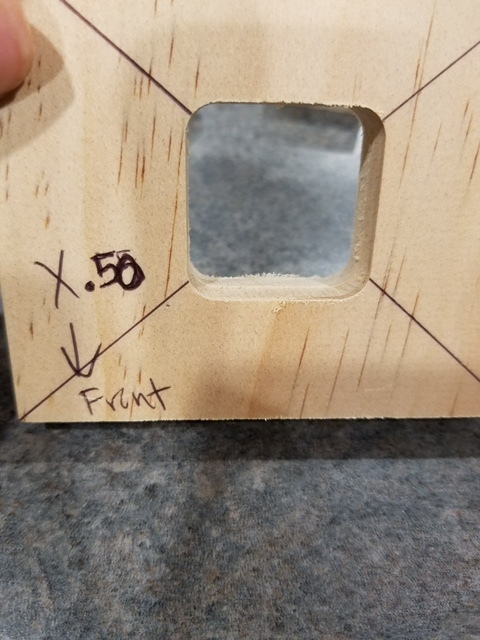
I have worked three seperate jobs, as well as a test cube I made to test this alignment issue. I have over 40 hours and numerous wasted jobs. It appears to be a very consistent mis alignment between the two sides. My thinking on day one was I needed to center the work in the flip jig with shims, and Rich very adamantly insisted I was wrong. I realize that now. I have messages in to Apollo but he is busy and I hope that an open forum discussion will help resolve the issue so the machine can be put to work.
I would gladly PayPal someone who can help solve this issue, at this point since I have not received much support other than to make sure I pull on the flip jig.
After thinking that the jig was creating an issue, I began placing my work in the bottom left (SW) corner and zeroing X Y by locating the edge, and then adding .159mm to center my .125" end mill to absolute zero SW corner. Using this method, the completed work is identical in mis alignment as if I was using the jig. At this point I would much prefer to work by locating the edges, and do away with the jig all together as it allows for more fixturing options. The one issue I see with edge finding, is if the stock is not squared up really well. If reference point at SW corner is taken and set 0,0 side A, and the work is flipped to side B and 0,0 is set and those two corners are not squared up it will create issues. Can anyone attest to this?
When using the flip jig, I rapid move to center, and then move X to the center of my work, being sure as to not move Y.
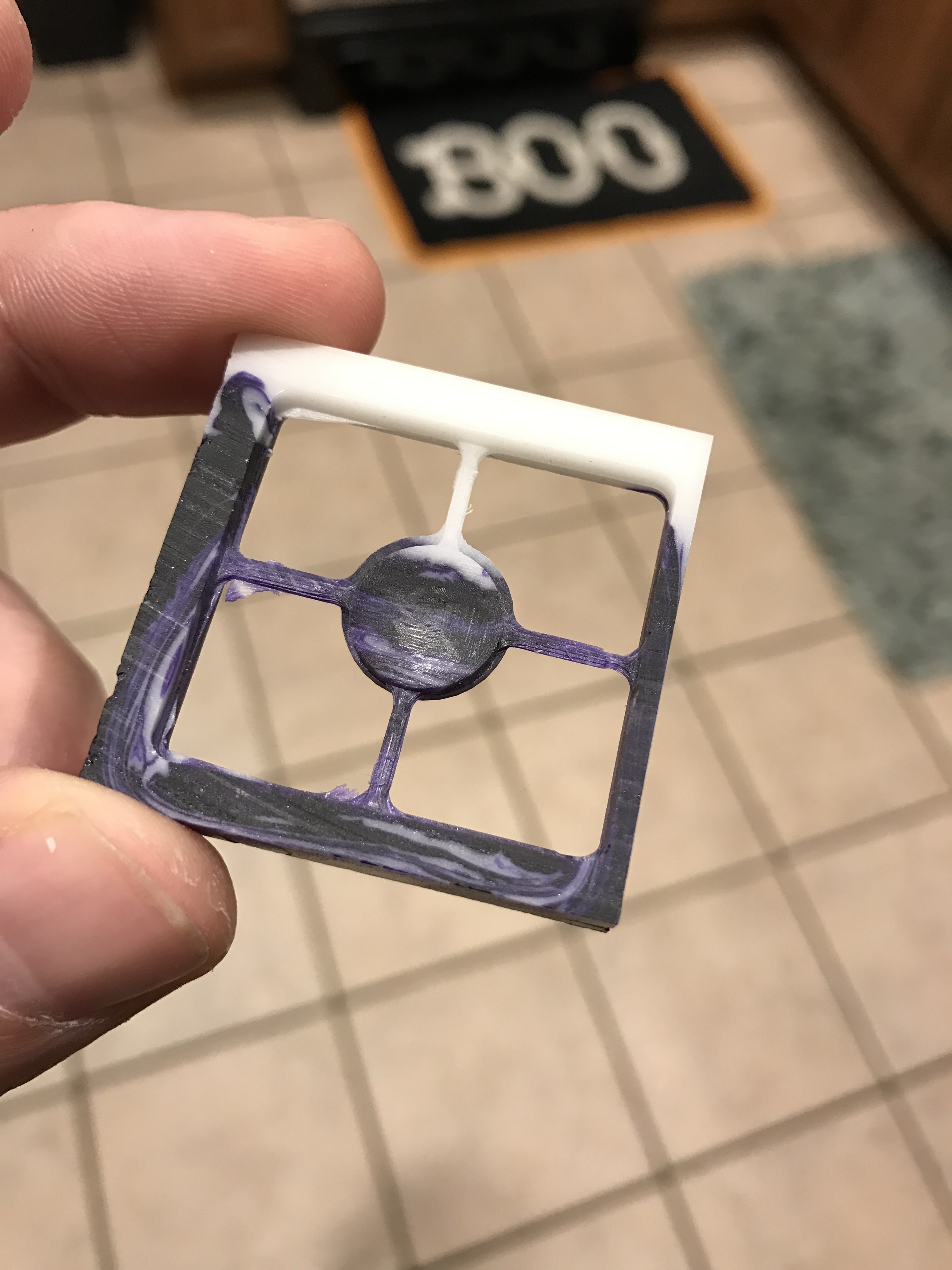
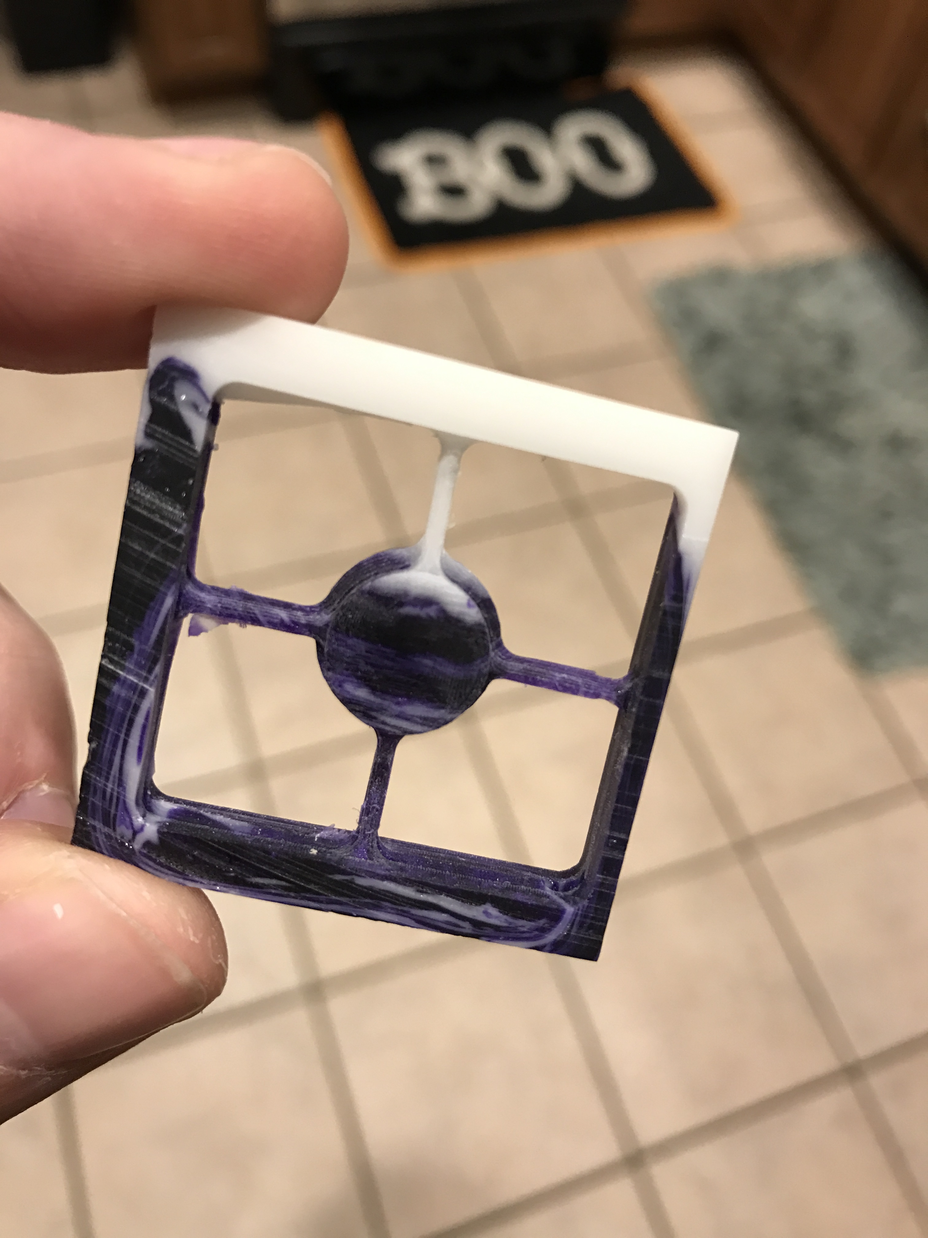
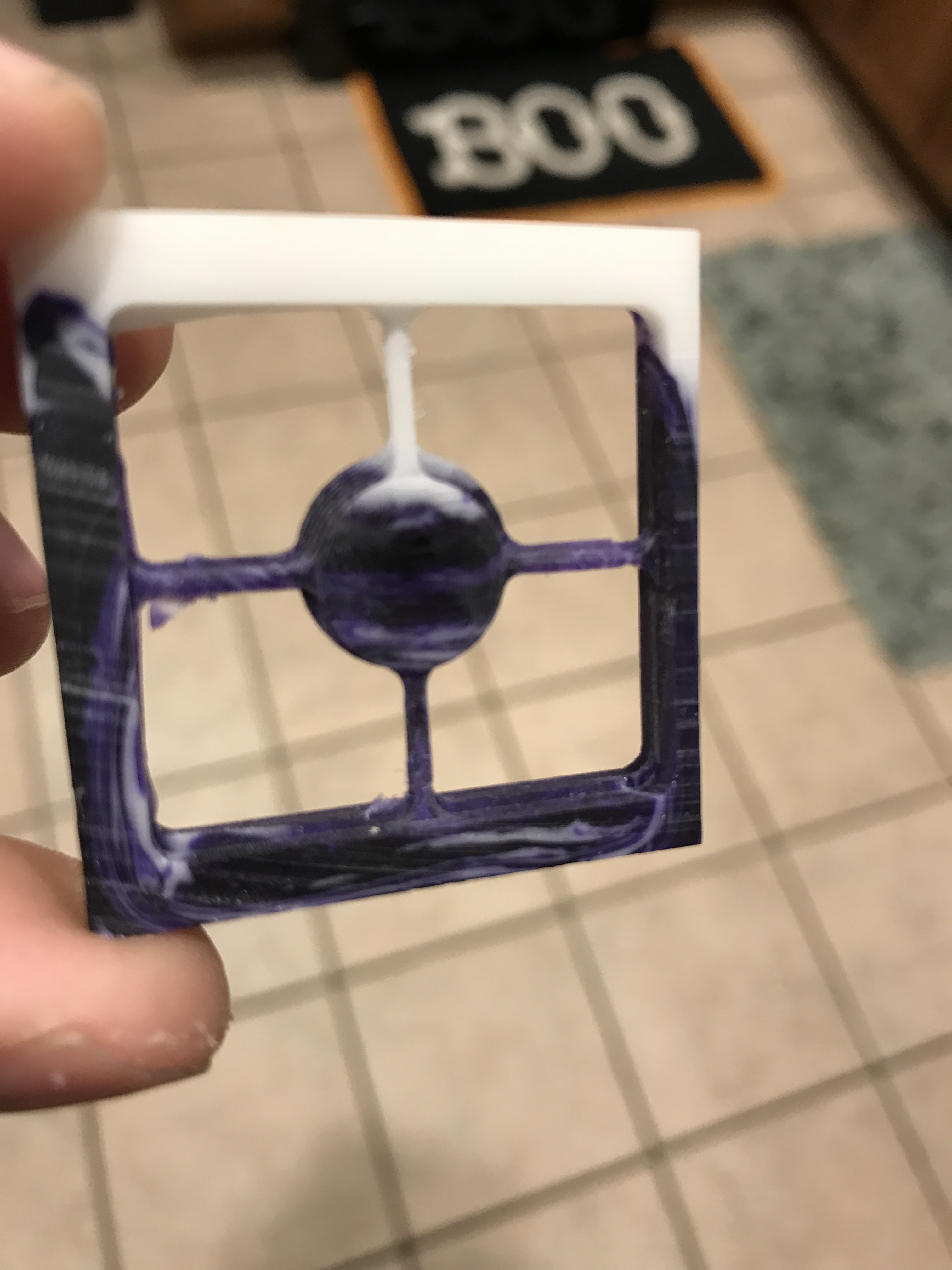
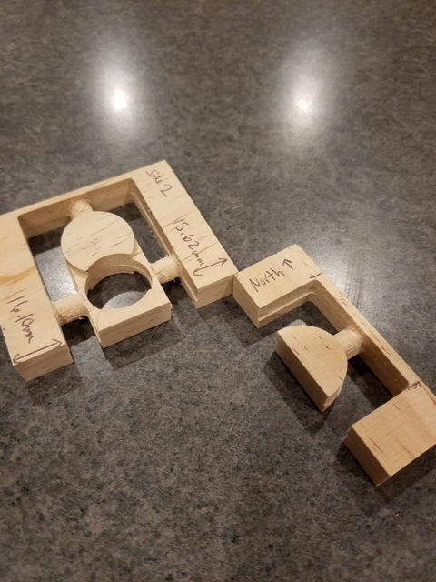
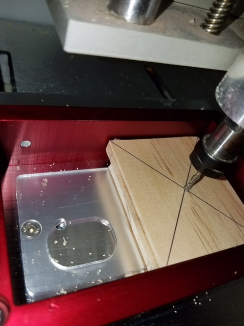
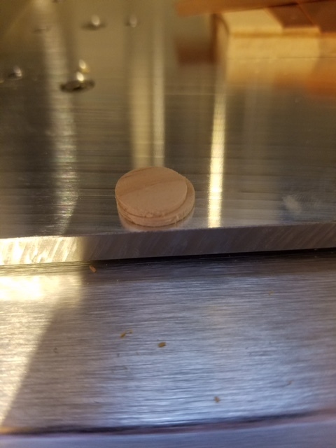
I will attach one of my most recent failed files. The support structures added are far from ideal for this very small part, however I added them to eliminate any issues with part movement. Typically I have moved the part to just below the surface of my rendered material in meshcam, created a file for side A, flipped the model and moved to bottom for side B. For all intensive purposes, I believe this file should work for troubleshooting purposes. Attached are only several pics of many failed jobs.
I do have a solid grasp on basic principals. I was a technician prior to real estate developer, and have worked on manual machines and lathes for many years. I have waited days before asking for help with this issue, but I have exhausted all possible ideas.
Again, anyone who can directly assist me in this I am more than willing to offer some money for your time, or possibly a flip jig which does not work for me.
I’ve used the flip jig successfully to do two sided milling. One of the things I did was to define my stock Y axis size as the interior of the flip jig (3") rather than the real stock size and then positioned the geometry using the margins in meshcam so that the geometry was closer to the bottom on one side and closer to the top when I flipped it.
I defined the work zero to be the center of the jig, so off center of the stock that’s being pushed against one side of the frame. Obviously, it’s important that this agree to within however much margin you’re allowing from the jig to the machining region (or you’ll machine your jig.)
I run one side, then flip the jig (pulling toward me and to the left while tightening the screws, same as the first side). Re-zero only Z and leaving X and Y alone. And then I run the other side.
I haven’t done it without the jig, but I think you’ve got to get where you don’t zero X & Y. That is, you use registration pins or edge and the machining on one side includes the holes and/or the machined edge to line up with your registration when you flip it over. Otherwise you need to use something very accurate to do the zeroes like an edge finder. Even with an edge finder, I think you’ll find that is sufficiently hard to square the part with the bed that it doesn’t line up.
One way to make squaring up the stock repeatable is to cut a pocket in your spoilboard to hold your stock. Even with the pocket though in order to flip accurately, your stock corners need to be square and the opposite sides need to be parallel and the Y-axis size needs to be known to the accuracy you want when you flip it. Of course, you can use your machine to square your stock and bring the sides into parallel.
@markwal
I did try what you suggest several days ago regarding define Y as 3". I used shims opposite the clamping screws to center the stock within the fixture.
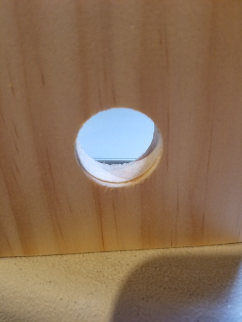
Nothing I have tried has gotten rid of this ridge.
I don’t understand why it’s not working for you. The only thing that matters here is that the registration pins on the flip jig line up with the registration pins on the other side. It seems unlikely that they’d be off by anywhere near a mm. Also, unlikely to be a whole mm of play in the pins either.
So assuming you’re only flipping around the X axis (the diamond pin stays on the same size) and you aren’t re-setting Y-zero on the second side, then why would it shift? Well, there’s steppers losing steps, but your buttons look round. The stock shifting in the jig, but that seems more likely to be along the X or Z axis, does’t it? Hmmm…
I’ll see if I can find the time to give your model a go at some point this week. I’ve got some scrap 6mm polycarbonate here I could try.
Maybe you can take one step back and see if it is your machine. If your approach is solid, then maybe that’s not the problem?
I don’t know if this will help, but is there any way that you can get two pieces of wood stock exactly the same? Maybe stack them on top of each other, screw them together, and then cut off all 4 sides with a saw? Then, you would have 2 pieces of wood with the exact same width and length. Mark the lower right corner of each piece as you unscrew them and separate them.
On your Nomad, set up a corner brace that the stock can be pressed against. Secure it and then cut a circle all the way through it. When done, move the cutter away, replace the first stock piece with the second, ensuring that your pencil mark is in the exact same spot. Recenter the spindle and run the same cutting job to cut the circle all the way through. When done, overlay the two pieces of stock again, screwing them together with the same holes as you did when you first trimmed them to size.
If the holes don’t line up, then the Nomad isn’t repeatable and there may be a small adjustment to a set screw or something else? I don’t know; I am just kind of rambling here. When I try to troubleshoot something like this, I try to break it down into basic pieces and then go through a process of elimination.
@1st_Kiwi_Nomad
Yes I’ve read @ApolloCrowe tutorial several times to be sure that I hadn’t missed anything. Hopefully he returns my messages. I am quite dissatisfied with the results at this point. My wife is questioning if I should have spent the money for this machine, as am I at this point. It doesn’t seem that you get much support after the sale, aside from the members of the forum. @markwal
Are you saying you set an offset to compensate for the gap between the front of the flip frame and stock? If so, how? Are you jogging the machine y or are you moving geometry in MeshCAM?
“ONLY use the X and The Z buttons only Jog to the Top Center of the stock”
That comes after doing “rapid position” to the center of the bed, which if your endstops and bed are aligned properly should put you precisely at the center of the flip jig (in Y). So perhaps the rapid to the center isn’t putting you at the center of the jig (in Y). The offset should be repeatable (assuming your endstop is repeatable), however, so if you can measure it, should be able to adjust for it by moving in Y slightly before zeroing.
I’m moving the geometry in MeshCAM. In the stock definition, I unclick “Center Y” and click “Fix stock dimensions” and then choose an appropriate bottom margin (ie to get the geometry far enough away from the jig).
Depends on which side you mill first. I mill the side with the stock holding screws away from me first, so the stock is in y- for the first side and y+ for the second side.
Yes Mark I agree with you. It appears that it clearly is not y0 when doing rapid to center movement. Hopefully @ApolloCrowe chimes in. I’m ready to give this machine back to them.
No. I just pull the number out of my, uh, head. Like 12mm. It doesn’t matter really except that I want enough room to put my machining rectangle around the geometry and still have some unmachined stock between the tool at the jig.
Of course, if your model geometry is closer to the size of the actual stock you’d want to be a bit more precise in the way you mention so that you fit within the stock at the other end. But so far I’ve had plenty of extra stock on both ends.
Interesting Mark. I thought you were making up for the gap at the south end, or in your case the north end since you begin screws away. It sounds like that’s not the reason. Could you please elaborate? I’m going to try this shortly.
No, it’s to avoid trying to get to fussy about making the stock be in the center.
I was going to do a run through of your part at some point and take pictures along the way.
For the flip lining up, it doesn’t matter if the stock or the geometry are centered. All that matters is that the Y=0 lines up. All the rest of the measuring just needs to only be as precise as the geometry fits inside the stock in the way it would for traditional, one-sided case.
Ok, maybe I will hold off on trying that. I thought it was doing something to compensate for the gap between the flip frame and the edge of my stock.
My machine when center shows a Y value of 107.39 off of memory. Can anyone else confirm this?
Maybe I have a Y axis issue. Hopefully @ApolloCrowe chimes in at some point and can offer troubleshooting.
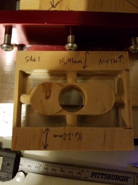
Seems like you have enough data to figure out how to offset your Y axis after doing the rapid. Now, the thing is, the margins on the top and the bottom on one side being different don’t mean anything. Those are going to be off because we’re not precision centering the stock. What matters is the difference between the margins on the flip sides. So if you use your calipers to measure one margin on both sides. (Make sure you’re measuring the same one on both sides, ie the one that was resting against the jig, not the screws.) You’ll also need to know which one you machined first.
So let’s say that the margin gets 0.5mm smaller on the second side. That means that you need to move Y=0 toward you by half of that distance. So you rapid to the center, move 0.25mm toward you and then zero-Y. Then use the stock to zero X and Z (but not Y) for the first side. Then only zero Z and run the second side.


 It doesn’t matter really except that I want enough room to put my machining rectangle around the geometry and still have some unmachined stock between the tool at the jig.