Hello all, been reading the forums for about 4 weeks. Just received my Nomad 883 Pro yesterday, and fired it up this morning. I am having an issue trying to run a program. I was successful running the wrench project, so I am sure I am missing a step on my end. The problem is that once I load my G code from MechCAM V6 to Carbide motion I am missing something and breaking tools. My details steps are below. I am a mechanical engineer with 20 years of CAD, but zero experience on a CNC, limited machine shop experience. Thank you in advance.
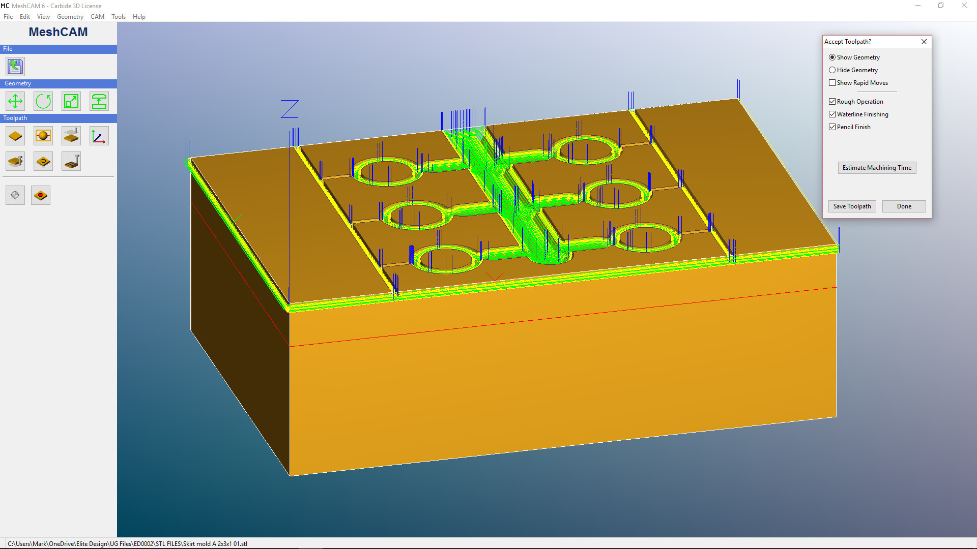
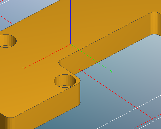
set up cutter path in MeshCAM, 0,0,0 is left,front,top as shown (I think? Just going off of WCS).
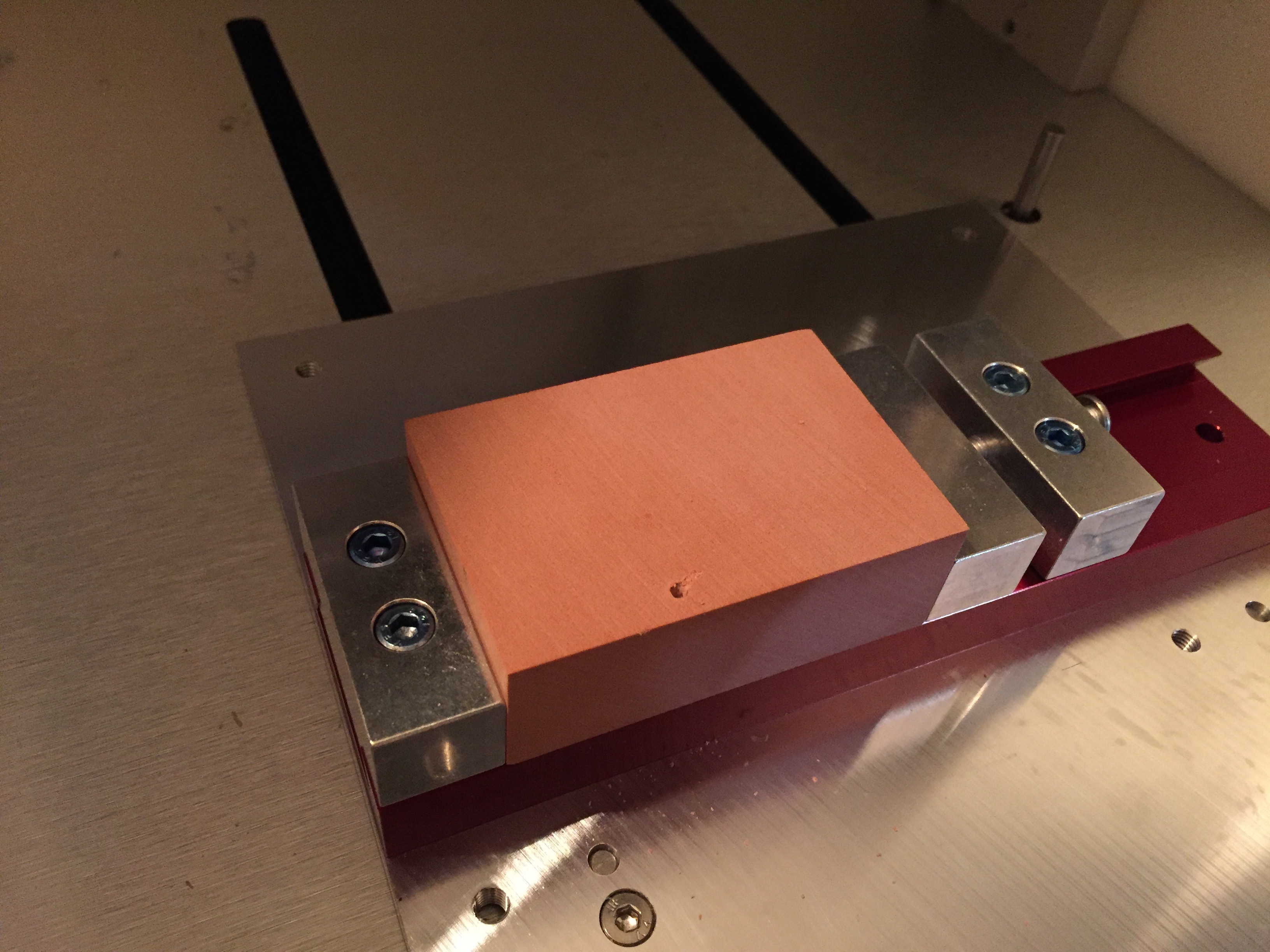
Lock work piece (Renboard from Carbide, 2"X3"X1", use 1/8 wobble indicator from Carbide to find X&Y edges, then insert cutter to find Z zero. Wait, thats my issue isnt it. I’m changing the Z length when changing from wobbler to cutter to find the Z axis.
When I run the program, the cutter digs into the stock and break my cutters.
So, I may of figured out why I am doing it wrong, but can anyone explain how to find Z? Or will Carbide Motion automatically calculate the difference in the cutter lengths when it checks it?
OK, I think I figured it out, I would like someone to confirm since I am waiting on more cutters from Kodiak anyway =(
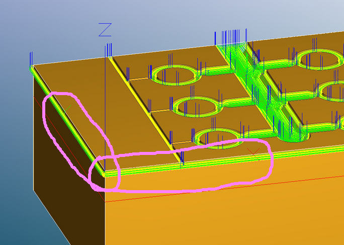
In the first picture you posted it looks like your zero is below the top of the work surface (red line you see around the perimeter of the part). If that is the case and you’ve told carbide motion that the zero is at the top of the part it will try to ram the cutter into the part down to that red line.
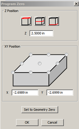
In MeshCam make sure you click on the top left box shown below which sets your part origin at the top of the part then don’t type anything else into the z, x or y dialog boxes shown.
When you do that you should see the z origin on your part move to the top surface.
I believe the red line is my maximum cut depth. I set that to protect the vice. I reloaded the program, set the Z axis with the wobbler this time, THEN changed the cutter after I started the file (when it asked me to) and it’s running good.
Thank you for the feedback Tshulthise, I thought the same thing one of the times I went back and tried to trouble shoot my problem, but noticed it was only the MAX cut depth making the red line.
I was going to delete the topic, but hoping it helps others.
However, my plunge rate seems slow during cutting, any input on that would be great. Trying to research everything on my own, but there is sooooo much information.
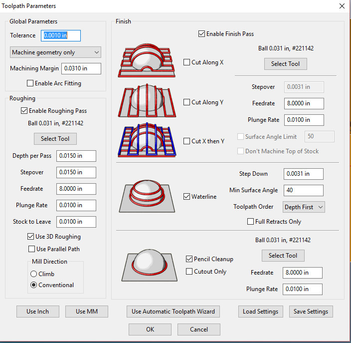
Is it moving slower than the three plunge rates set at in MeshCam Toolpath parameters? There are 3 places to set the plunge rate in the Toolpath parameters. It may be that you have it set slow on one of them that you didn’t see. Just guessing though.
About the zero setting… I’ve had some gouging issues with the machine zeros not being reliable if I don’t set them right before I run the job. Apparently others aren’t having that issue enough to post about it. They say Carbide Motion saves the zeros on the computer so my issue may be related to my particular setup somehow. I always set my machine zeros right before I run the job just to be sure. I haven’t had any issues when I do it that way.
I think there are several requests in to have the axes in MeshCam show up better. Hopefully that will be implemented sometime soon.
I can see my x and y axes on the top of the part in MeshCam when I set the top of the part as zero. I don’t see that in the picture you posted.
Also, if you cycle power to the machine you need to restart Carbide Motion. It doesn’t tell you that its lost connection but it goes a little haywire when you cycle power on the machine then try to use CM without restarting it. I consider that a bug but I know about it so I always restart it just to be safe. If you cycled power on the machine and didn’t restart CM that could have caused the problem you saw too.
Hopefully one of those two things will take care of it.
CM will take care of it for the Nomad. For Shapeoko systems you have to reset z after each tool change (which CM doesn’t currently allow you to do).
The X and Y origin vectors are present in @Mark’s screenshot.
Unfortunately, MeshCAM is stuck in the “single-pixel-width” mode lately so even if you select “fat” origin ( Edit | Preferences \ Show Full Program Zero ) it doesn’t apply.
The plunge rate is only effective for the first movement downwards from the Retract Height, not every downwards movement.
Plunge rate is slow because you have it set to .01"/minute. try 2.0 inches to start (it’ll still be slower than you really need, could probably be about half the feed rate)
Thanks guys. Still learning. I did confirm the XYZ was correct in MeshCAM, and after I figured out that the Nomad is smarter then I am I was able to get it to run. I will try to up my plunge rate to two. I went very conservative at first, but I way missed the mark.
One more question, how long of a continuous cut time is to long? I am working on my settings trying to get everything in it’s sweat spot, but after about 3 hours on that job the spindle housing was warm to the touch. The original program was going to be 33 hours to cut which too long, but is there a MAX run time I should look at?
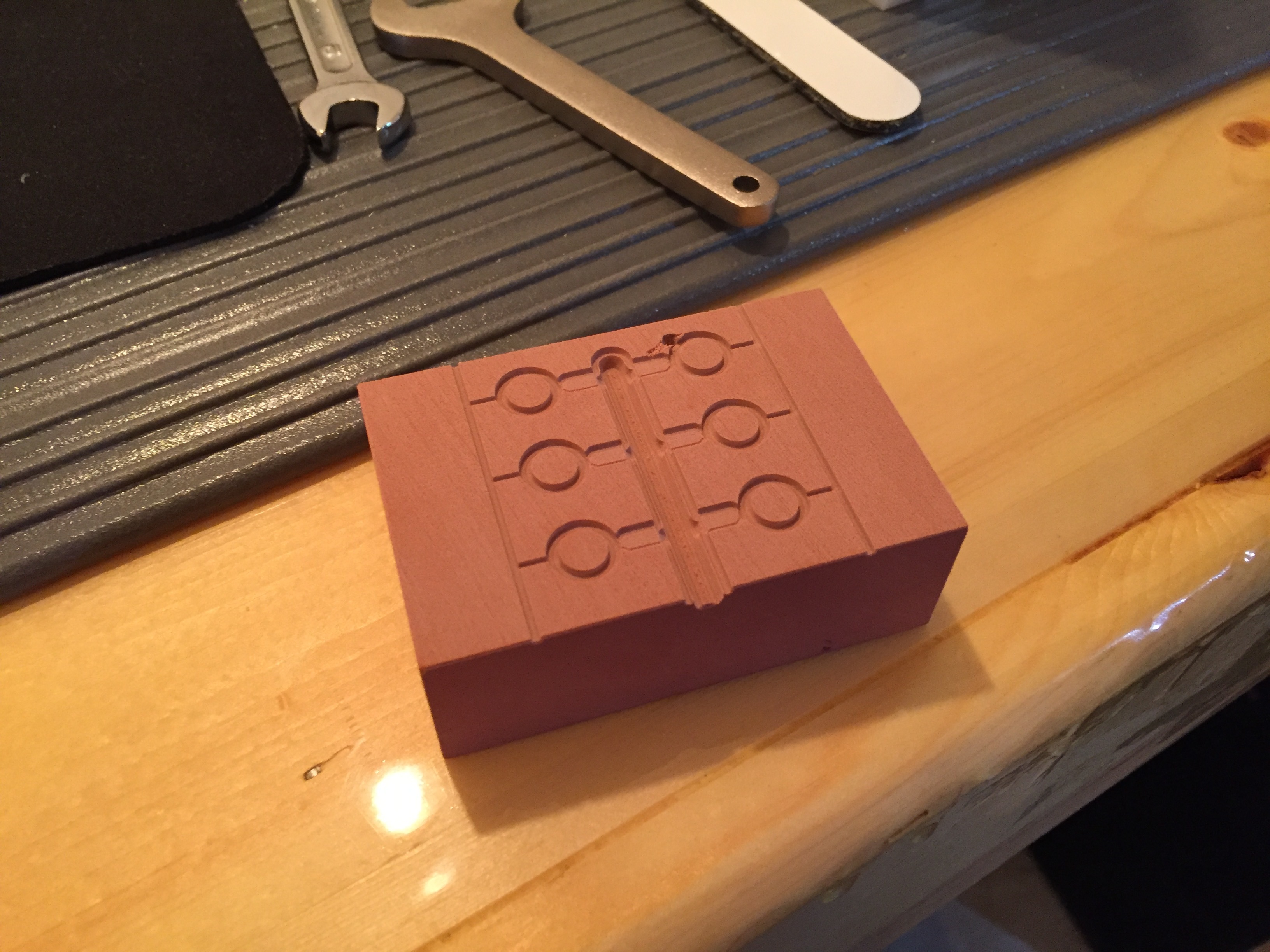
Adding a photo of the finished part. It was on a damaged block (you can see a hole from the Z axis problem), and there are a couple of small fins that didnt get machined out, but for my second job im very happy with it.
Thanks, thought it was for all downward movement. Trying to find a good source for all of the terms, and when to use what finishing methods. Been reading a lot on CNC cookbook.
Good question but I doubt that you can overheat the spindle motor. Most stepper motors are fine even when they are too hot to touch. I don’t know that I would feel comfortable leaving a job unattended for very long though. Something as simple as a screw coming loose could crash a job which could lead to a fire hazard in just the wrong combination of circumstances. The Nomad doesn’t have much power so that is unlikely but it is possible.
You might look into a program called GWizard. It will let you set your feeds and speeds to minimize cycle times. I don’t remember if it gives you plunge rates or not. In any case, plunge rate can affect cycle times more than anything else if you set it too slow, especially if you have the retract height set very high. I usually set the plunge rate conservative for the roughing pass and much more aggressive for successive finishing steps since much less material is being removed in those steps. You will get a feel for all of this as you watch the machine go through several jobs.
You might look into a program called GWizard… I don’t remember if it gives you plunge rates or not.
It does. To the right of the feed rate.
I’ve done jobs as long as 9 hours. The spindle was warm but not hot. Others have run for many hours.
I don’t know that I would feel comfortable leaving a job unattended for very long though. Something as simple as a screw coming loose could crash a job which could lead to a fire hazard in just the wrong combination of circumstances.
One of the fundamental rules of CNC work is to stay within eye and ear shot of the machine when it is running. Failure to do so can result in serious issues including machine damage and fire.
I know of two people who started fires with their CNC machines. One lost their entire detached garage and workshop.
Never leave a run machine unattended.
What material are you cutting? The feed (how fast to move into the material) and speed (the RPM) depend on several factors including the capabilities of the spindle, the characteristics of the machine tool (“emd mill”), and the material being cut.
Do not go guessing about feeds and speeds, nor simply accept what others say works for them. That some time to learn the basics, it’s not hard (and we can help).
Going slow is not necessarily better. In fact, it can actually make a mess of your stock (material). Each material, end mill, and spindle has several solutions that provide good to excellent results.
In CNC terminology, plunge rate usually refers to the feed rate in which the cutter is cutting downward into the part past the R-plane. The Machine Rapids to the R-plane also termed as “Rapid Plane” before and after cutting/drilling/pecking into the part. Since MeshCam is very basic and doesn’t appear to use most canned cycles, or it uses the R-Plane as the initial starting point (I believe it uses it as the initial Z clearance point) you always want to act as if the Plunge rate is cutting material.
In most advanced programs or when hand-writing good code there will be an initial Z retract clearance plane along with an R-plane where the cutter starts it’s plunge-rate. (plunge-rate is the cutting feed downwards.)