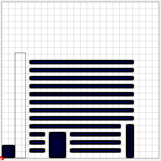
However when I visualize the project in UGS I’m getting this result:
Please view the image in my own reply post below as I can only include one image as a new user.
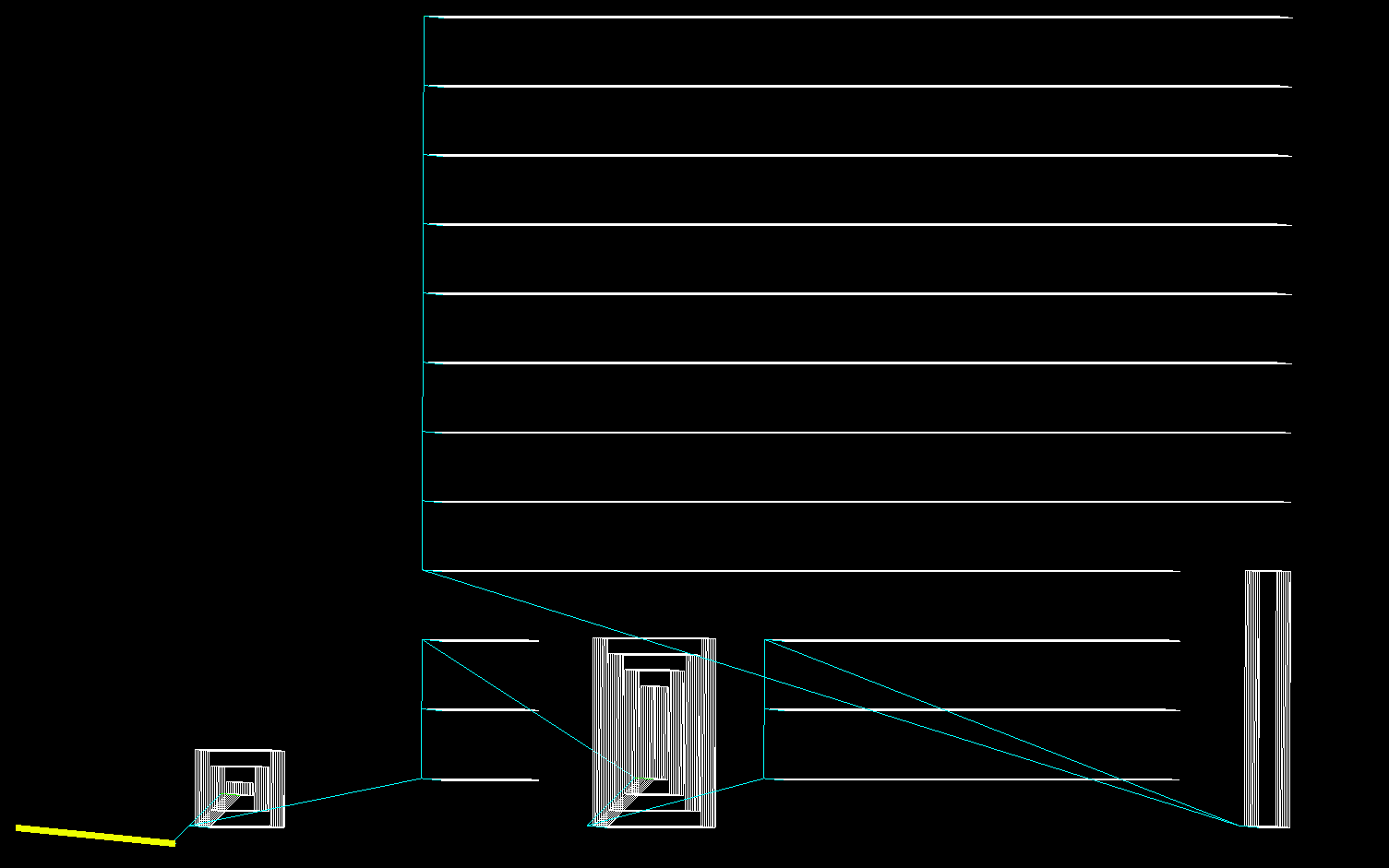
Note the yellow line which indicates the endmill starting position. From this image it looks the endmill will be moved a few mm to the top right before it will start cutting. Does anyone have an explanation for this? I haven’t tested the actual job yet.
funky… Does it do that if you run an “air job”? Zero it a safe distance above the work and run it… Or, try Camotics which has an AWESOME gcode visualizer; http://camotics.org/download.html
It looks like the lines in the UGS preview line up with the blue lines in CC to me. I think the offset you’re noticing is because the radius of the bit isn’t shown in UGS. If this was a profile operation instead of a pocket you would see the yellow tool moves towards Y- instead of Y+ for the same reason.
The visualizer in the UGS Platform version has an improved visualizer with grid lines which might make it a little easier to inspect your program.
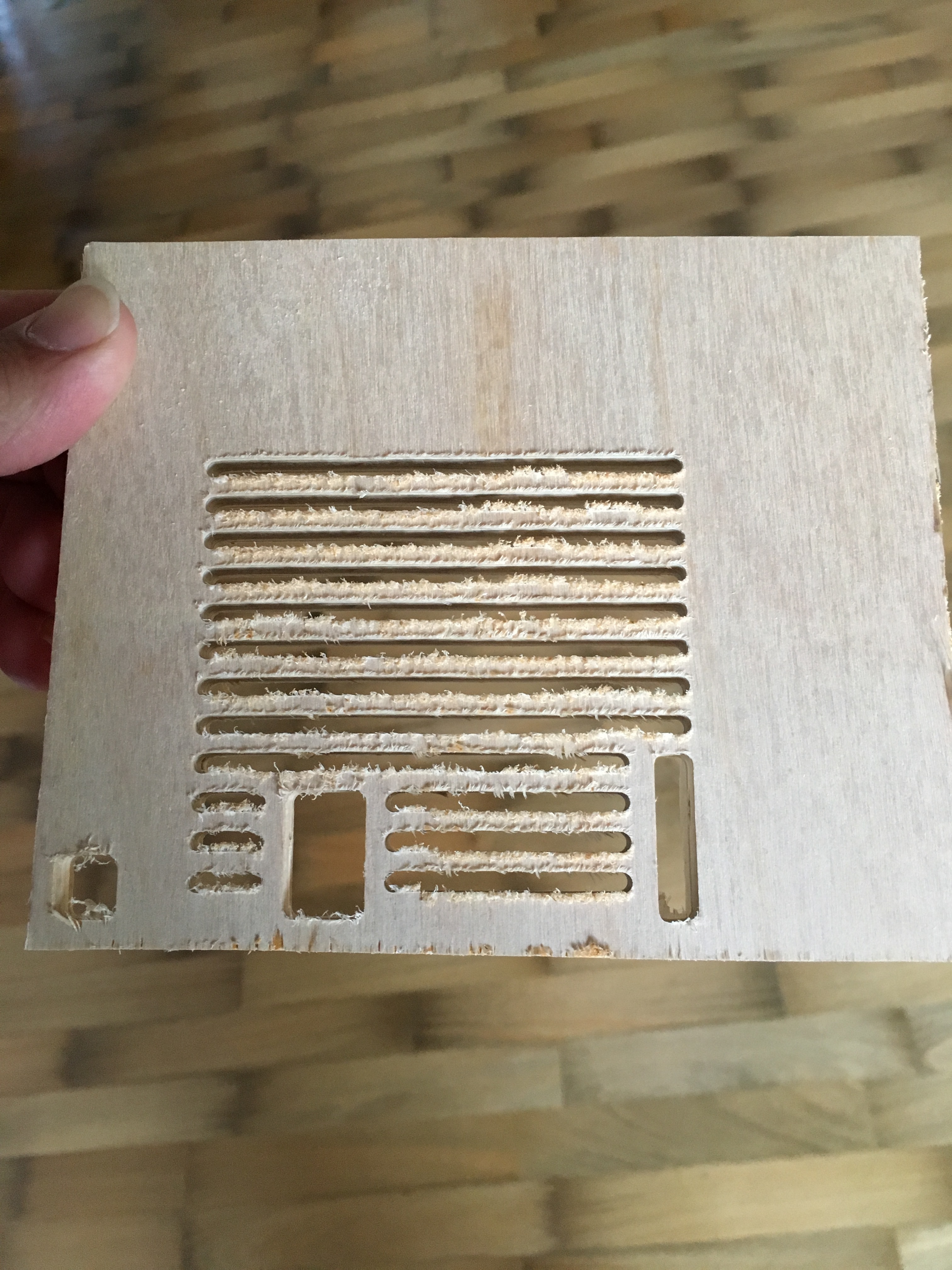
I went ahead and ran a test job on some scrap 8mm plywood. I didn’t mess with the feeds and speeds suggested for soft wood in CC just to see what the end result would look like.
The good news is the milling does start where toolpath zero is specified. So looks like you were correct @Winder. The bad news is that it looks like the feedrate was too high as you can see in the image below.
I used a two flute endmill which I’ve used with success in the past around 200mm pr minute. I believe CC suggested nearly 300. At this speed chips would slowly build up around the endmill during the 45 minutes it took to complete the job. Would it make sense to use a four flute endmill for smoother finish? I guess that would need a slower feedrate.
So much depends on tool geometry… I’m guessing you’re using a .125" end mill here? 200mm/m sounds quite slow to me for that material, but it also depends on your pass depth.
I love all the attempts made to come up with Unified feed and speed charts, but IME making your own for your bits and machine (using the published ones as a starting point) is the way to go.
FWIW, on what looks like cheap plywood, you’re going to get those fuzzies on the edge anytime you use an up-cut endmill. Almost every endmill out there is upcut unless specifically specified as a down-cut endmill. If you lightly sand that surface, how does the cut look?