Hey! That could be a picture of my machine when I milled the dust head! 
mark
Hey! That could be a picture of my machine when I milled the dust head!
mark
I’m running a HDPE job now with the dust head, the Festool CT26, the 50 mm external tubing and 1.5" internal tubing. I’m going essentially 100% pickup running the CT26 at full blast.
I’ve got a nice negative pressure on the enclosure too - perfect for friable materials!
Have you had a chance to experiment with more gentle curves and an improved transition?
mark
I ran a small job that I designed a while back (before my Nomad arrived) two nights ago and used the CT26 running at ~80%. The material was one of the free Home Depot flooring samples…so plastic. Probably not the best material to test with…shavings were a little big and while some were sucked up immediately, others just joined a growing pool near the Nomad bed.
I did play around with the front cover, opening it a little and then closing it a little…so I have a better idea of the air needed for the vacuum now. I need to work on getting the 50 mm hose a tad closer to the rear. My desk isn’t much deeper than the depth of the Nomad, so that’s why I was curious about the angled fitting for the transition between tubing. I think what I have now is good (nowhere near a right angle), but for my testing I just left it longer than was needed.
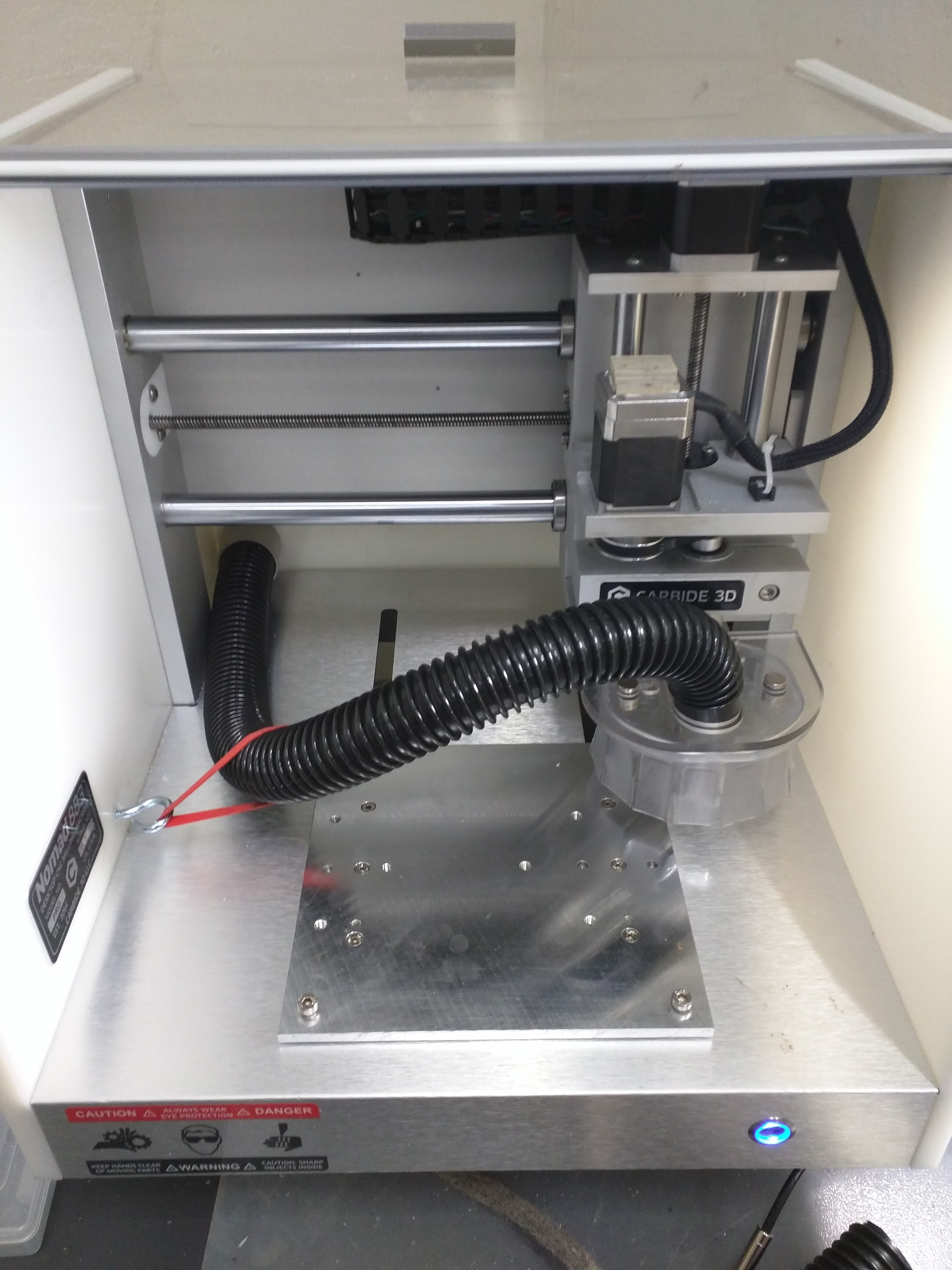
Inside the Nomad is a little bit of an issue. I can’t seem to figure out any way to take out the sharp angle leading to the dust head. When at left, there is so little room that it can’t help but be angled because I have to leave enough tubing inside the Nomad to stretch to the other side when closest to the measuring pin.
I’m convinced that a custom case is the way to go, I just have no idea when I’ll get around to that. I wish the Nomad’s case didn’t angle on the front and was boxy like the Carvey (https://www.inventables.com/technologies/carvey).
Inside the Nomad is a little bit of an issue. I can’t seem to figure out any way to take out the sharp angle leading to the dust head. When at left, there is so little room that it can’t help but be angled because I have to leave enough tubing inside the Nomad to stretch to the other side when closest to the measuring pin.
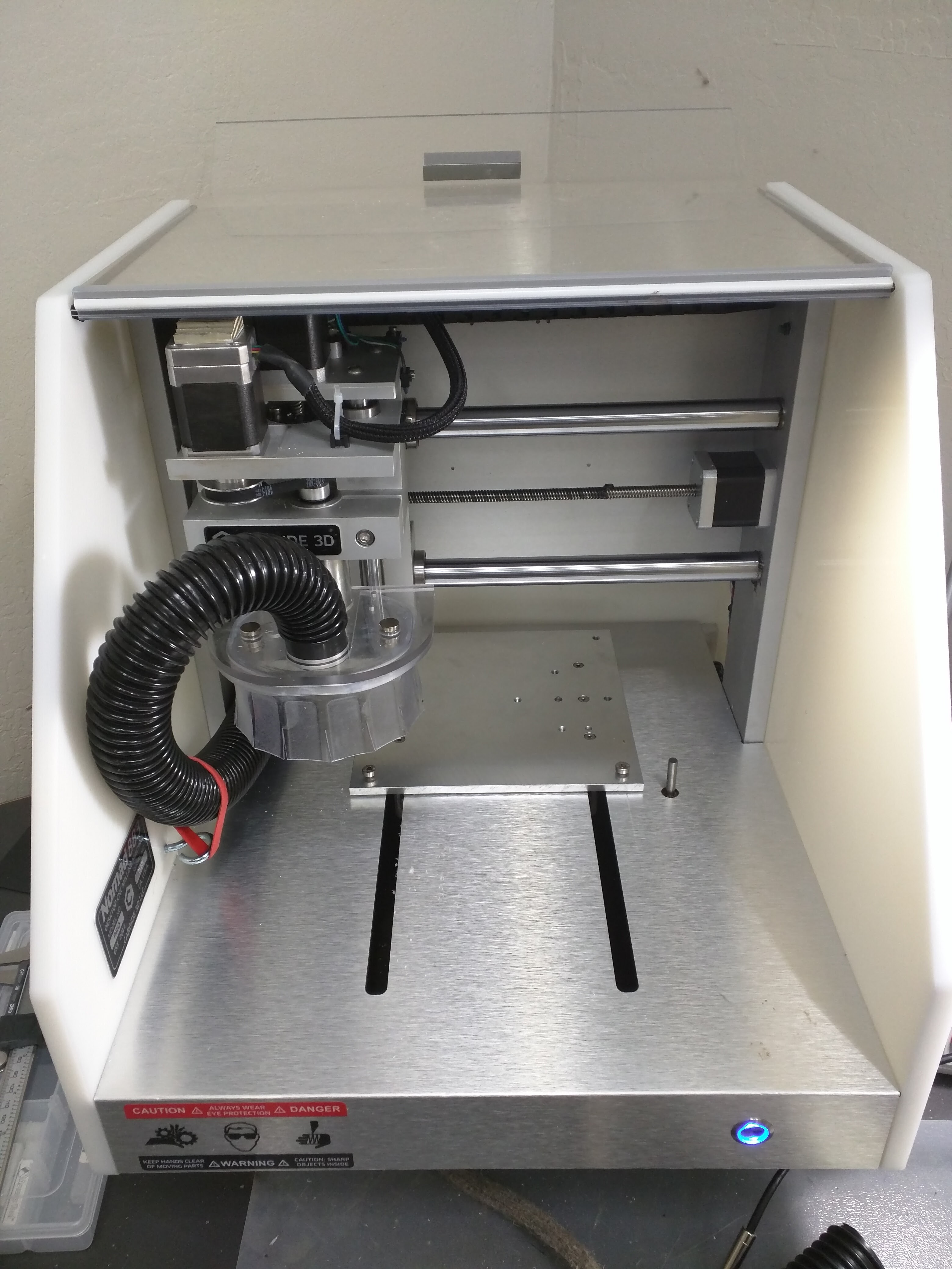
The Nomad 883 had considerably more room inside. You can see this in the @patofoto pictures. The Nomad 883 Pro has many improvements that increase its stability and quality, decreased part count,
and it easier to machine (create).
I was very happy about those improvements! Then I also discovered that the enclosure was much smaller! @patofoto can tell that I went nuts for weeks trying different schemes trying to use the Nomad 883 Pro enclosure. I gave up. There may be a solution… but I didn’t see it and see don;t see it.
The tight curve of the tubing inside the enclosure is almost definitely the remaining issue. A custom enclosure can solve that issue. I’ll be happy to help you with enclosure design. My solution was to increase the the width and depth slightly and raise the height by 6+ inches. The additional height allows the tubing to enter from the right front, near the top and gently curve down to the dust head.
mark
We just added c2d and zip to the allowed file list in the forum so it should work now. By default, the software doesn’t allow much so we’ve been adding additional file types as needed.
Also, shoot an email to support with your Carbide Create bugs. We’ll do what we can to get them taken care of.
-Rob
when i load the STL file for the spindle bracket it shows stock dimensions as 1" x 1.25 " y and 1" z.
is that correct ? also how to define the red supports ? can you post your support and define stock screens in meshcam.
also the other parts show 4" and 5.25" instead of 6.25" and 5.25"
thanks
When I load the STL file for the spindle bracket it shows stock dimensions as 1" x, 1.25 " y, and 1" z. Is that correct ?
Correct.
How to define the red supports ?
Those are done with support button - top row under Toolpath, second from the left. They are easy to erase and start over so do experiment until you get comfortable.
Can you post your support
That is what I posted. One needs to look at the image and add the supports to match.
and define stock screens in meshcam.
Add 0.25" around X and Y - all around - for all parts. This is in the text.
Inclusion and exclusion is the second button from the left, lowest row.
also the other parts show 4" and 5.25" instead of 6.25" and 5.25"
That is correct. The stock allows for the construction tabs and clamps should people want to use them.
mark
support height 0.25" support width 0.25" and bottom of geometry ? the red lines are much thicker than your picture of the spindle bracket.
also why did you say we need 3" x 3" x 1" stock if we are only going to be using < 2" of it ?
Support height 0.25" support width 0.25" and bottom of geometry ? the red lines are much thicker than your picture of the spindle bracket.
The support height and width of 0.1" and bottom of geometry. I updated the text to make this clear; the 0.25" was a typo. Overkill.
also why did you say we need 3" x 3" x 1" stock if we are only going to be using < 2" of it ?
I used step blocks and clamps and needed more clearance. Even so, you’re correct. It’s overkill. I updated the text and set things to 2.5" x 2.5". That is more reasonable.
mark
thanks. also exclusion regions and inclusion regions – will they serve any purpose if i am just using carpet tape to stick the plastic blocks of material or do they serve another purpose ? i assume they are for avoiding your clamps ?
Thanks. also exclusion regions and inclusion regions – will they serve any purpose if I am just using carpet tape to stick the plastic blocks of material or do they serve another purpose? I assume they are for avoiding your clamps?
Notice the “machine whole stock”? This will remove all of the stock that is not geometry (the part).
The inclusion ensures that machining will affect everything inside (leaving the tabs). The exclusion for the corners of the top and bottom plates excludes stock that is a waste to machine… this saves a LOT of time.
Another reason things are done this way is to ensure that the large openings are machined away. This prevents anything from coming loose and potentially ruining the part and/or breaking an end mill.
Finally, since I wanted to save a LOT of time, the exclusion regions made a perfect place for some of the clamps (but I could have done it without depending on this).
mark
P.S.
I’ve said it it in many places in the forum - I have a nasty bias against tape and wax. I NEVER use them (unless I am forced; which is just about never). They do not hold well on larger and faster machines and gum up my expensive end mills.
I have a sea-of-holes bed for by Nomad and use step blocks and clamps, or screws to fixture most of my parts. The Nomad vise works for some things too. I machine a jig when I need to do something complex.
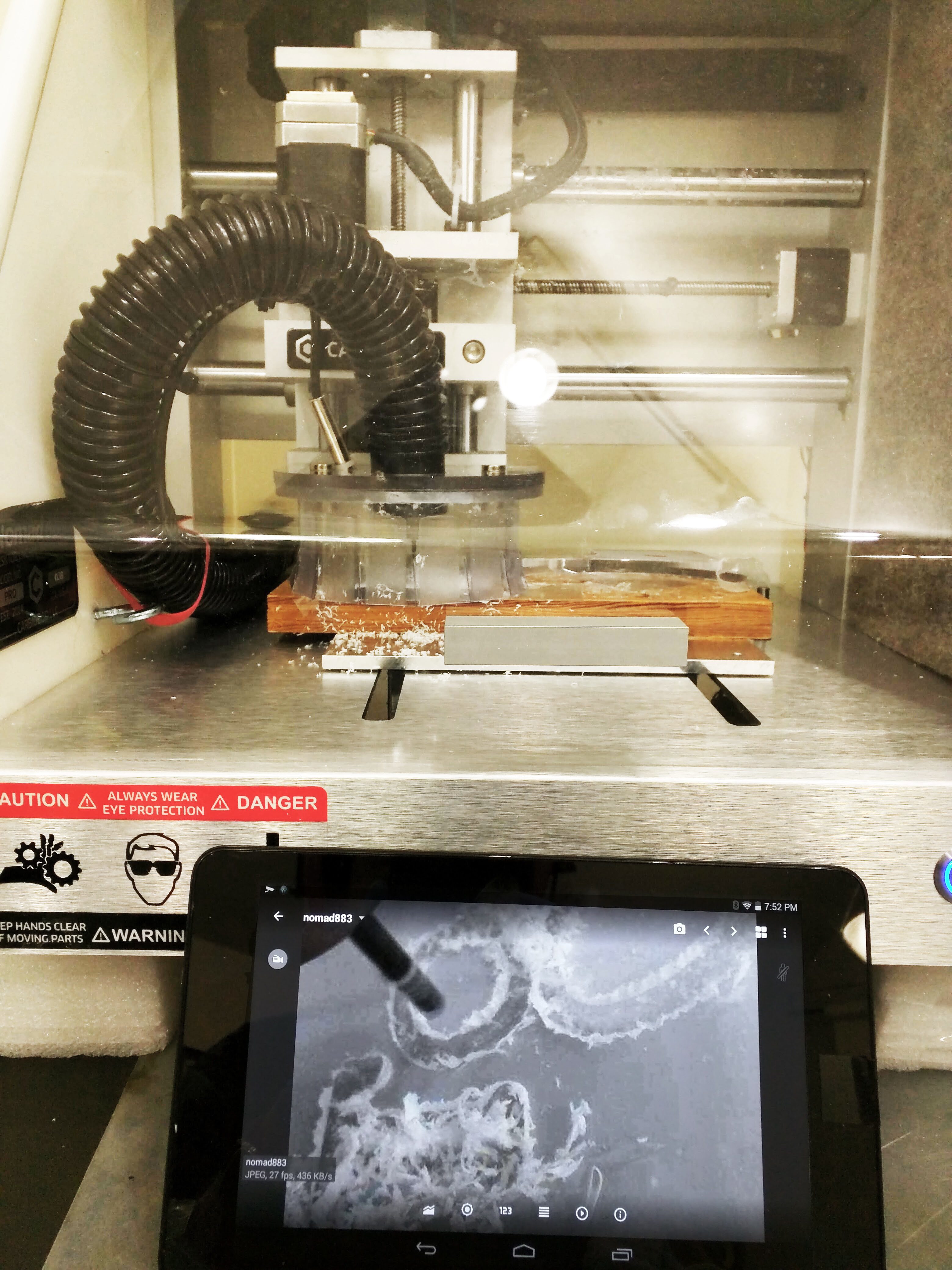
I just edited my Carbide Create version with a ZIP file now that the forum allows this. Today I bought a $4.12 coupler at Home Depot for the back of my Nomad 883 Pro and finished allowing the suction to go out the back of the Nomad. Basically I’m following the direction that “dyelton”, Donavon Yelton took. While the tube will touch the plastic protective door, it doesn’t seem to lift it which is good for me. Here’s a brocolli rubber band method that I am using to keep the tube under control and works well at least for me.
Far right example
The screw eye and rubber band - LOVE IT! Broccoli is cool with me…
Question: Why not put the screw eye higher (caulk up the old hole) and pull the tubing a bit more upwards?
mark
Man, thanks Mark. I held the rubber band to different spaces on the wall, and having the rubber band at different points on the tube before finally drilling. It seemed to work well in my case at the point I put the hole with the rubber band where it is seen in the image. When I had it higher, it ran the risk of being really close to my dust head. I wanted to have it tuck the tube underneath the vacuum dust head when the head moved to the far left-hand side of the Nomad.
Thanks again for this project. It’s been fun, very insightful and, of course, helpful keeping the debris/dust away.
I held the rubber band to different spaces on the wall, and having the rubber band at different points on the tube before finally drilling. It seemed to work well in my case at the point I put the hole with the rubber band where it is seen in the image. When I had it higher, it ran the risk of being really close to my dust head. I wanted to have it tuck the tube underneath the vacuum dust head when the head moved to the far left-hand side of the Nomad.
Gotcha. Nicely done!
mark
Like so many things I have been meaning to do, I’ve been meaning to add this.
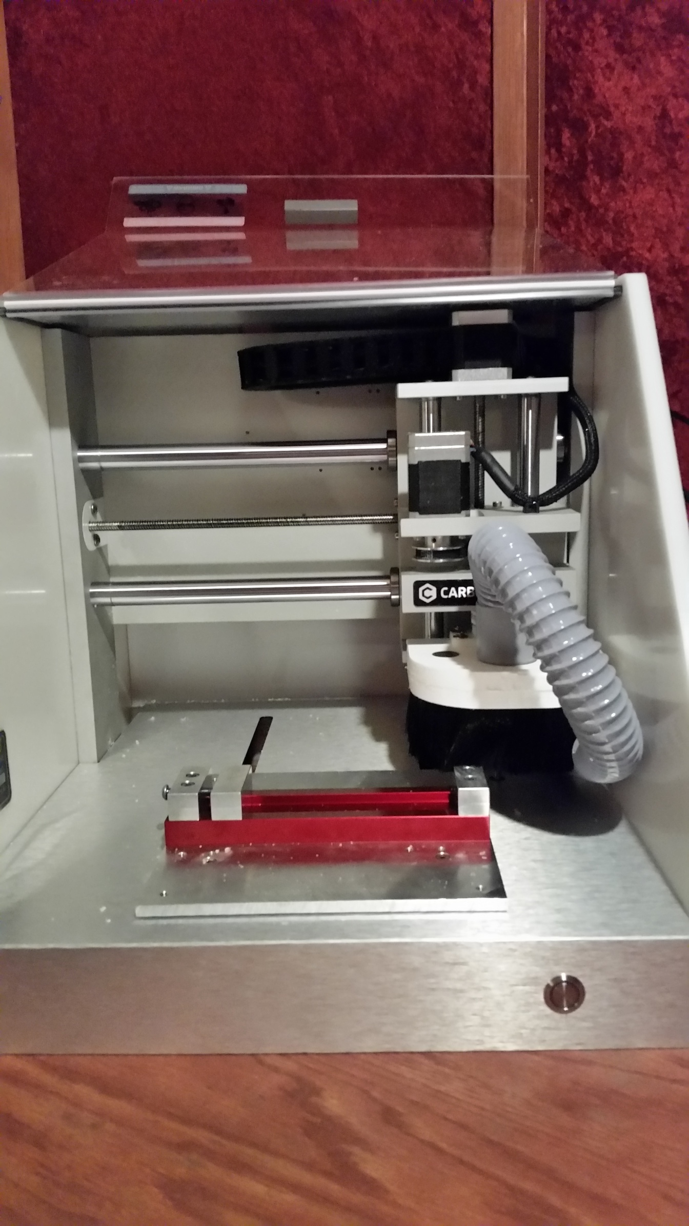
When I made my dusthead, I ran the tubing out of the back right of the enclosure. A lot of my reasoning was just to see if it would work. Also, it fits better with how my work area is set up. With that being said, it does work, quite well, but I would advise most not to do it.
Anytime you do a homing cycle you have to unplug the tube or it wont be able to retract all the way to the right. (Edit: I know someone will say something, in the picture I opened the cover, and manually oriented the tube to see if it could actually make it. It will not do that on its own) Not really a big problem, but it can be annoying. Also anytime the head goes past the right side of the work area, the tube will press the cover open somewhat. If it can make it all the way to the right without sticking, that “somewhat” is a few inches. Again, not really a problem, as once it is running it stays above the work area.
Pros: the tube physically can’t get near the endmill while it is running, and theoretically I’m using less hose than coming in from the left, which means better suction.
So more information for the group, do with it as you will.
Thanks for sharing. Good stuff to know.
mark
Hi Mark,
Can you upload step files of your dust head parts to this thread? I’m planning to make one of these today and have different magnets on hand so I plan to modify the pocket size if I can get those step files from you. I’ll start with the spindle brackets for now!
Can you upload step files of your dust head parts to this thread?
The original plans and STL files are:
I’ll add the STEP files there as well. I think it best to keep the data in the same place.
BBIAB, have to play with my CAD package…
mark
Here are the CAD files, as STEP files, is someone wishes to modify the design to suite themselves.
Archive.zip (33.8 KB)