This seems like a simple question but I can’t find anything here.
Can I connect my router to a simple toggle switch (through the power cord), turn the switch on the router to ON, then use my toggle switch to turn the router on and off?
I’m making a box that i’ll mount to my table in a convenient location. It’ll include an e-stop, a switch for my vacuum, and if okay, a switch for my router.
Yes, so long as the switch provides full current (don’t use a router control box which reduces current to reduce speed — that doesn’t work with, and may damage the soft-start circuitry).
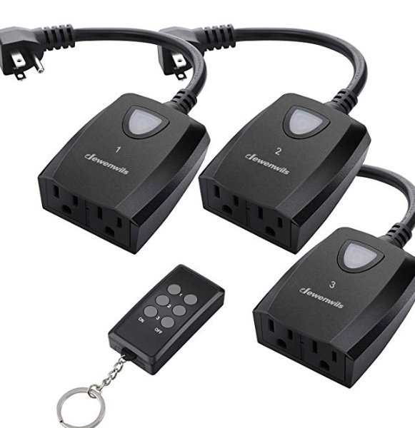
I have that same IoT relay. Even without using the PWM output to do control via g-code, it can be handy.
I connect it through a cheap e-stop’s NC contacts and also a separate “router enable” switch (in the same small enclosure mounted above the Shapeoko), and I connected the NO contacts to “feed hold” on the controller. Mashing that button kills the router power and does the “door open” hold on Carbide Motion, which is what I generally want when I’m working. In normal workflows, to enable or disable the router, I just toggle the little enable switch.
Since “feed hold” does not stop rapid moves in progress, having a “real” e-stop that cuts everything can save your bacon or at least possibly mitigate bad things, but a “pan-pan” button for feed hold and router power is convenient when you want to call an urgent timeout but not necessarily a full “mayday”. I rather like my “not quite an emergency, but timeout!” button, and being new at this, I’ve used it a few times.
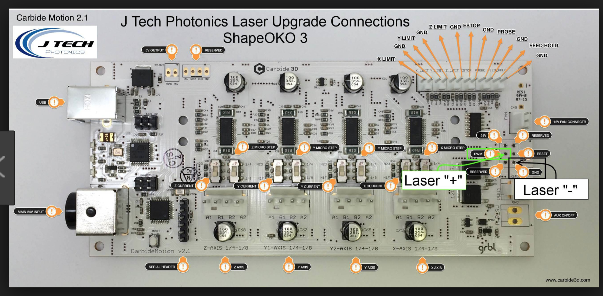
Your board might not look EXACTLY like this, but it’ll be close. The section that matters is over on the right end (it’s actually the spindle connector used on Nomad) Use the “laser +”/PWM output from here, and a ground, the “Laser -”/GND is handy. The PWM goes to the “+” input on the IOT switch, and the GND goes to the IOT “-” input.
Those look like holes. Are they? Do you just poke a wire into there, or some sort of pin, or do I have to solder something? I’ll check it out on my machine tomorrow but I’m kind of curious right now.
Yes, you have to solder something. There are no pins for this. If you have a 2.4d/e board, there’s a pin hole that’s actually labeled “PWM” above that connector (just found it tonight…)
The two photos of the 2.4e board attached in the EStop thread (post 4) show a set of four pins just above the “RESERVED” connector (that’s used for the Carbide 3D Touch Probe), with PWM and GND available. I didn’t take a photo of my board before I closed everything up, but I think the photos in that thread are stock.