Your bit may not be perfectly square to your table. I struggled with this at one time and ended up finding out that I had significant runout in my router spindle to the tune of about .0017" to begin with. I worked on squaring the router to the table and when I thought I had it perfect it was still about .0010". I removed that router and put my normal shop hand held router in and it completely eliminated those kind of lines. It was very frustrating to figure this out and I purchased some new bearings and lower components for the Dewalt DW-611 router to see if I could rebuild it and get it working closer to design but had neck surgery and have not be able to go into the shop.
Get you a cheap dial indicator and stand and order a bit calibration bit from Precise bits or a bit you know isnt bent at all and check the runout. It wont take much runout to see lines like that.
Bonch thanks for the additional steps to try. Will obviously try increasing the finishing pass cut first but now that I have the issue showing up on one side it makes sense it could be that. Few more things to try before I buy more stuff though!
I feel your pain there on the buying. I have been trying to setup my shop for some retirement earnings for next year when I retire and I have had to stop looking at advertisements and catalogs. I spent all my retirement savings LOL. Wish you were close I would certainly loan you what you need to diagnose if that is the problem. I left out that I also bought the precise collets for my router but that didnt make any difference in the runout but did eliminate the potential.
Hope you find out what it is. It really doesnt take much to make things show up on the front cutting surface or sides when things are not in alignment. And some things really exaggerate the about of calibration that it is off.
There is another way to measure the runout if you have a micrometer to measure the exact size of your cutting surface on your bit. I think you can use calipers also but it is not as accurate if my memory serves me correctly. Let me know if you do and I will see if I can find it.
One pretty simple way but not as accurate and one more complex but should point you in the right direction.
Runout
A quick first pass at determining runout is to simply cut a slot and measure it and compare it to the endmill diameter.
Alternately, cut a 4" square out of the material in question, then measure both the square and the resulting hole — half the difference is the effective cutting width[2], less the endmill diameter is runout.
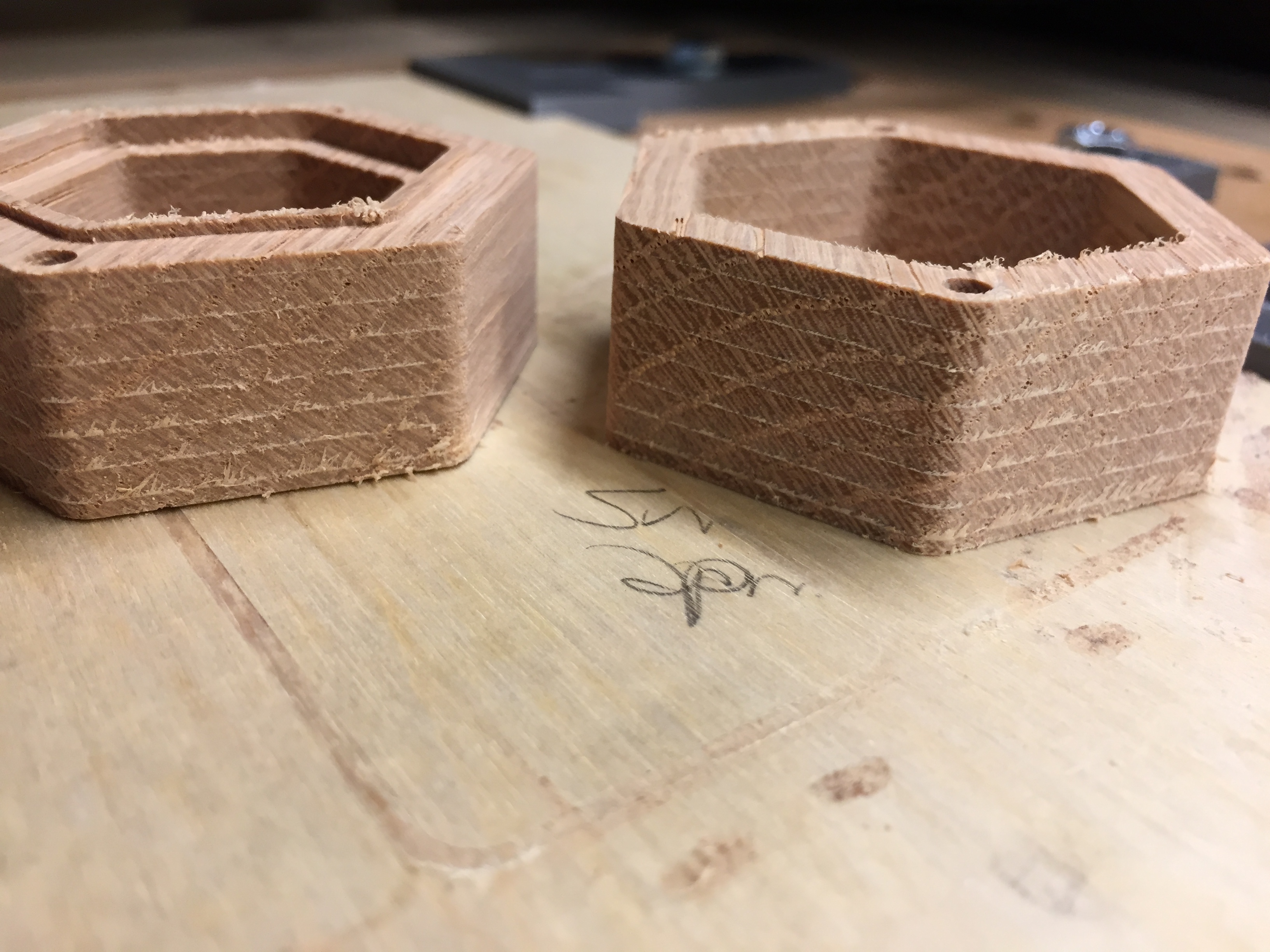
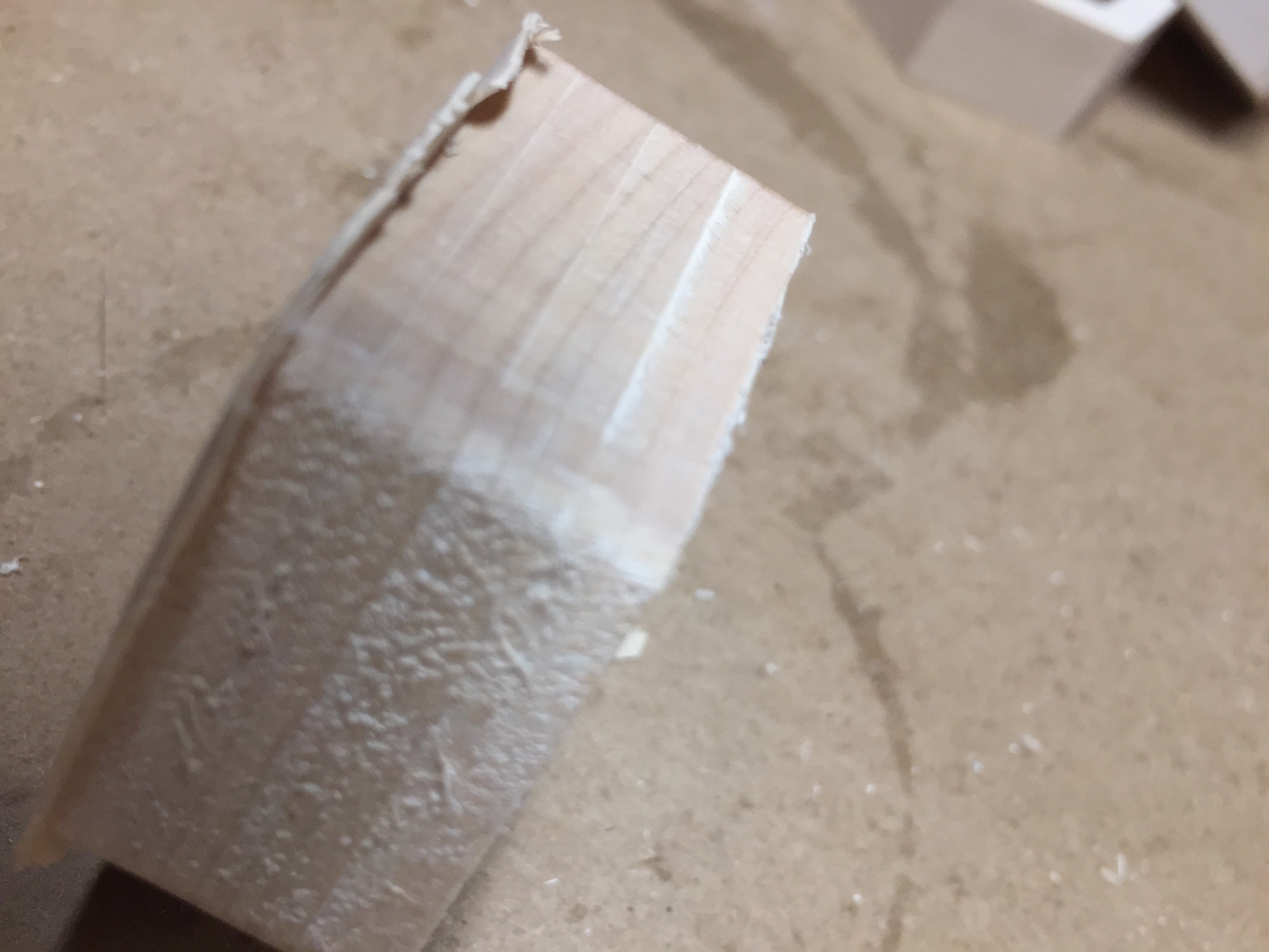
And this is my favorite the left two sides clearly cleaned up, not perfectly but reasonably well, the opposite face untouched. I mean I get run out and such but I’m surprised with .01" it’s not making contact. Most likely scenario I would think is the router isn’t perpendicular to the cutting surface which I know was mentioned above. Unfortunately either the issue at hand or the process I’m using to do the finishing pass also seems to be leaving tear out on the piece that I can’t even fix with sanding, since a piece is missing
If anyone’s curious about looking at the file and seeing if I’m doing something boneheaded I don’t mind sharing it. I may go back to the default CC settings for the feed&speed just to see what happens. They’re super conservative but I’d like to get 2 boxes made for gifts then I can explore it more. I’ve had this on other projects so I need to find a solution, these are just the first where sanding it extensively isn’t an option.
Sorry for the flurry of replies. I decided to go down to my shop area and look things over without running the machine. Best I could tell with my machinist square the bit was running true, and figured I’d check in the morning by rigging up a dial indicator. However when I was checking things over I realized the whole gantry seemed to have more play than I’d expect, I could easily tilt it back to front. I gave the two lower eccentric nuts an 1/8th of a turn and it all became a lot stiffer and deflecting it at all takes a lot more force. I checked out some pine test cuts I did last week and while it’s less pronounced it’s there so I think tomorrow I’ll try just routing out some squares in pine and seeing if that made any difference.
Alright setup a 1" test square, it didn’t go all the way through so have to kind of look in the trough here but, my Kodiak bit after tightening the v-wheels:
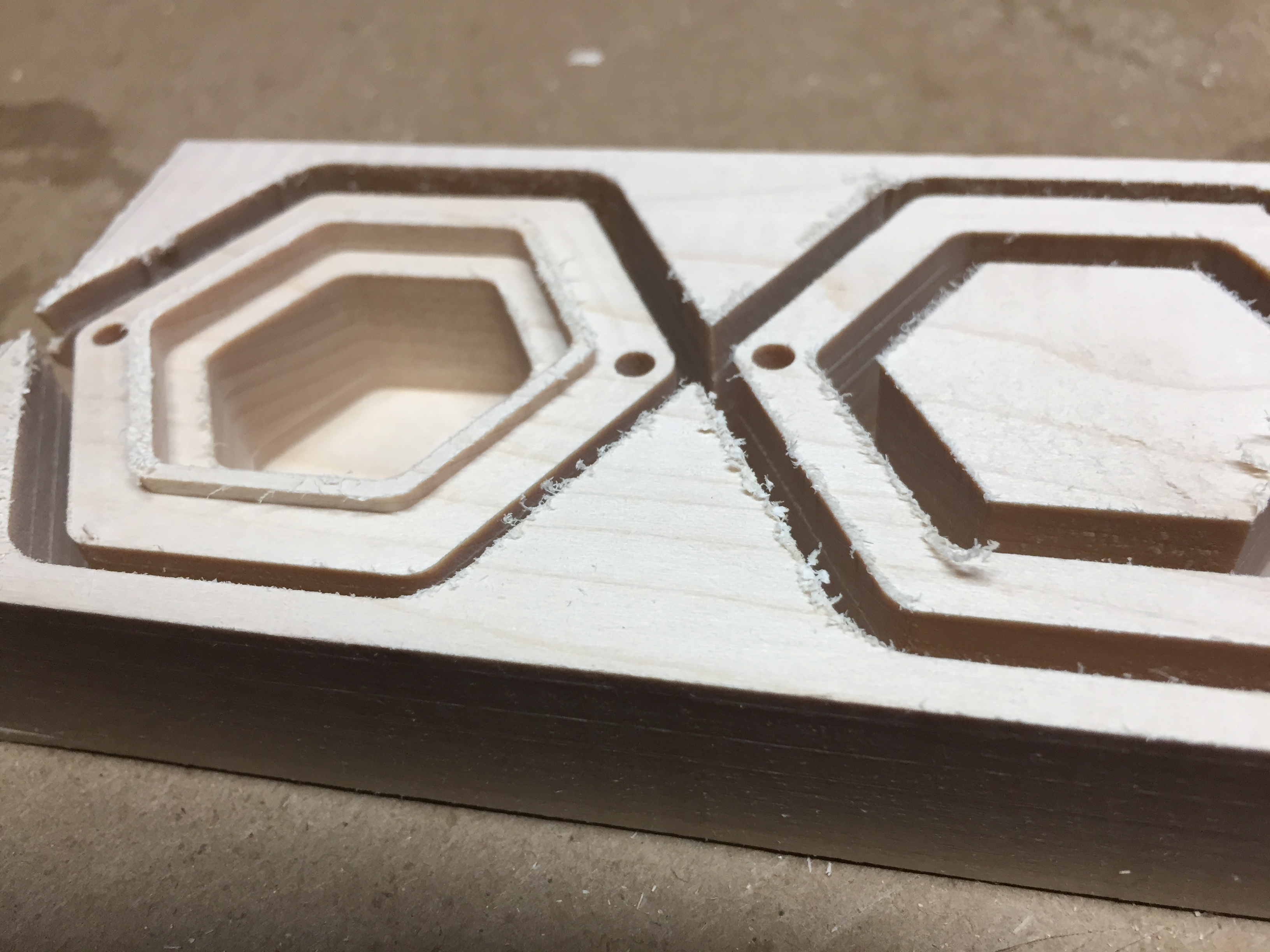
About the same, noticable ridges and while the angle doesn’t show it it’s on both sides. Now the Kodiak bit is the second one I tried, the previous one was a cheapo (the 10 bits for about $10 variety) which were similar. But hey threw in a Carbide3D bit and …
So at some point you ran the other bit too hard and bent it. It doesnt take much. Glad you figured it out. I wish there was a troubleshooting guide or flow chart but sometimes it is just trial and error.
Perhaps, they were brand new bits though in all 3 instances. Either way just did a test cut and had very minimal ridges show up and I think that was from an issue with the file that ran one part of it with too deep a cut. Hopefully that didn’t bend another bit To be honest from what I saw the ridges stuck out not in, which isn’t how I’d expect an endmill to bend if under pressure but doesn’t matter. Redoing a bunch of stuff to skip the finishing pass and just run as a normal cut and then will try it in maple again.
It seems to me that if some bits are giving you a ridge and others not, that the bits giving you the ridge haven’t been machined perfectly straight, they have an (unintentional) profile where the D of the end of the bit (for instance) is a little proud.
Yeah that’s what I’m thinking too. Took me awhile to get there because I thought I’d eliminated the bit issue by trying two different ones, but took till the 3rd to get a different result… I’m curious how the next attempt comes out.
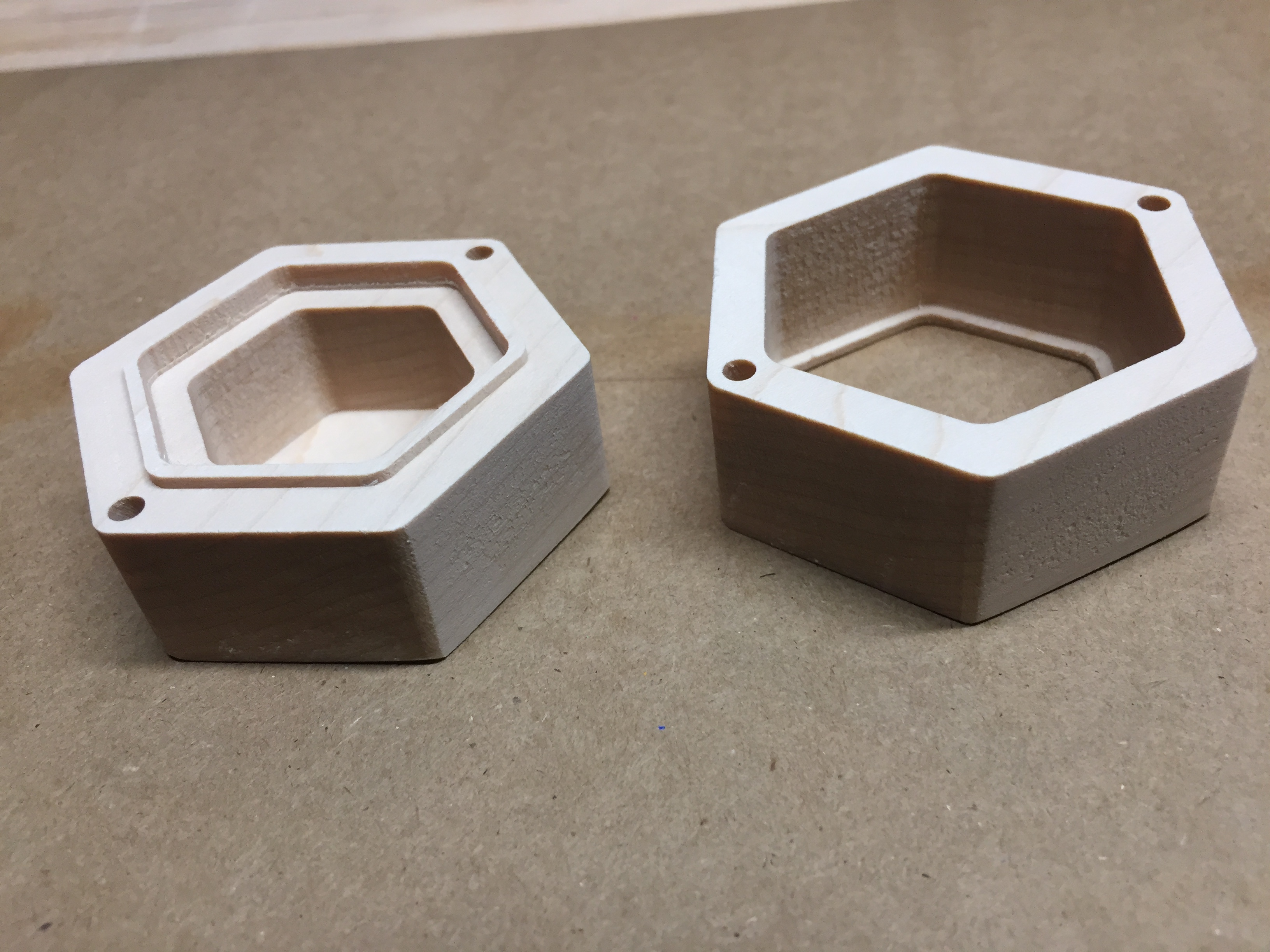
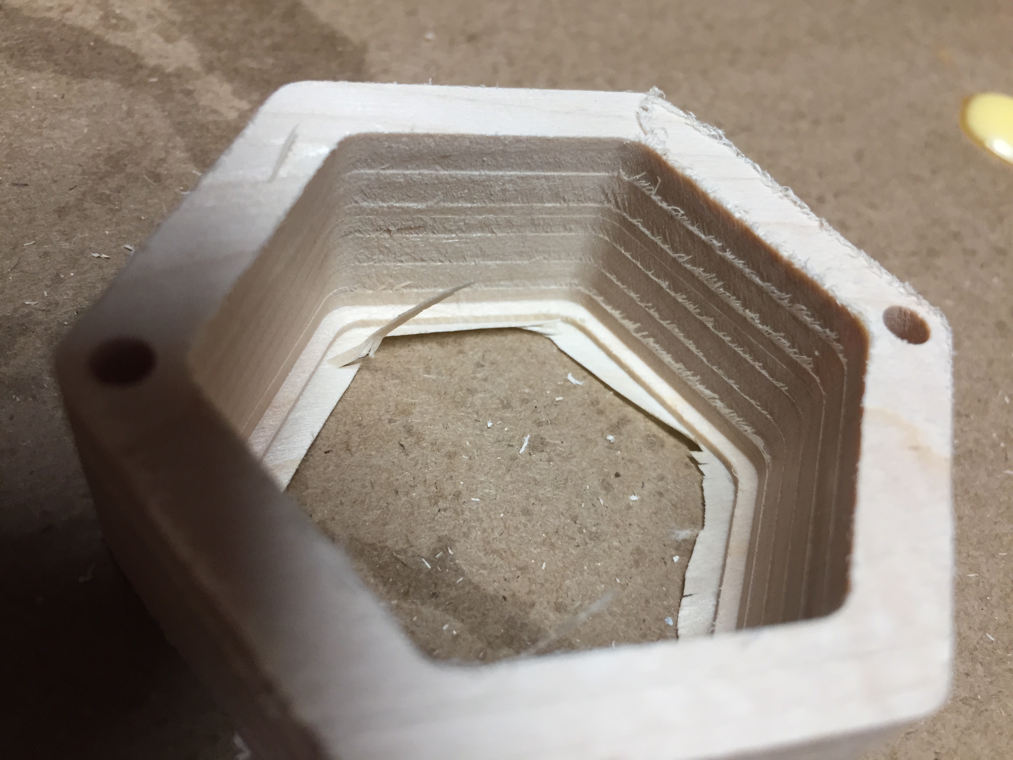
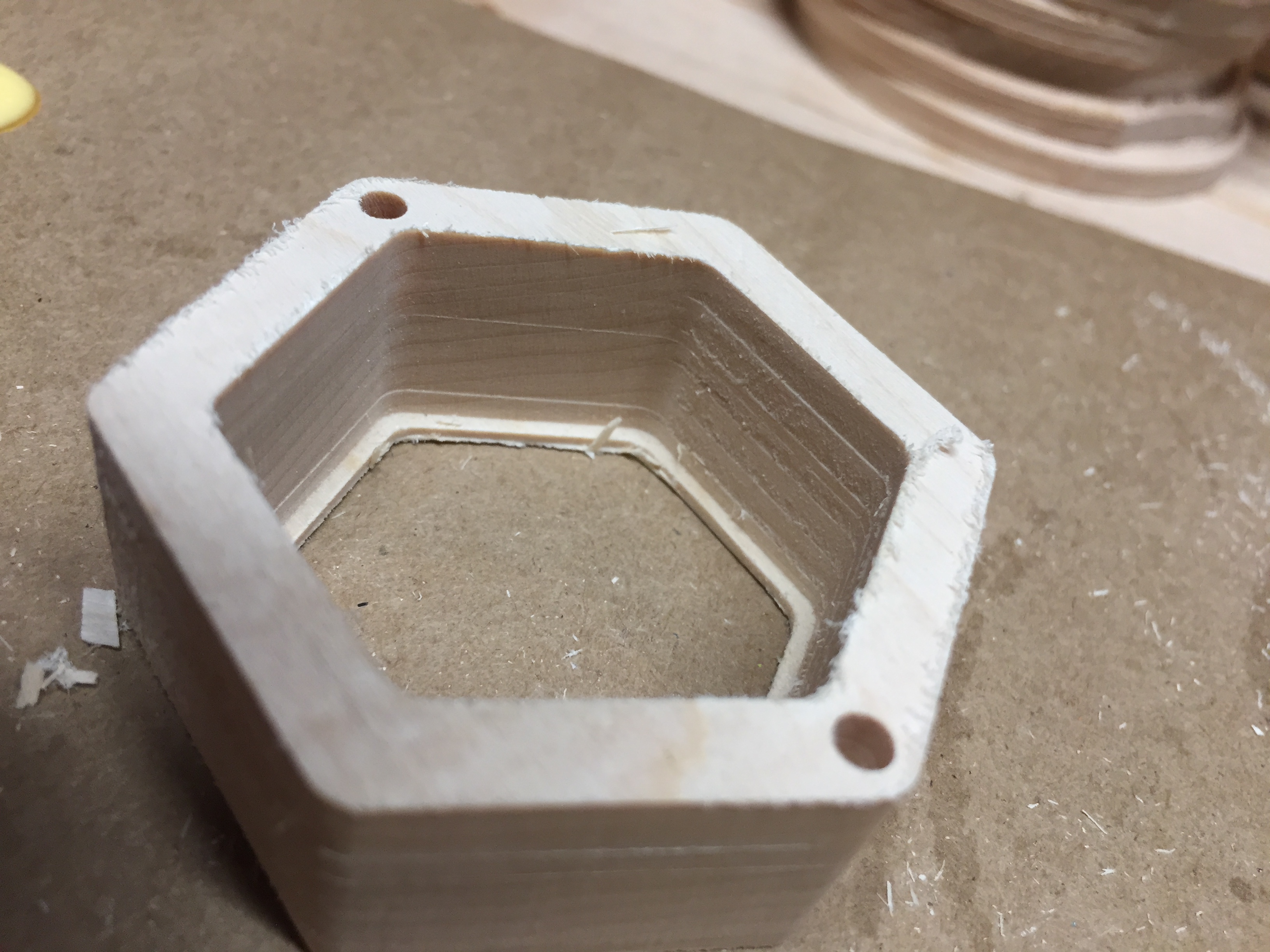
Confirmed that this fixed it, added more workholding and tried it in maple and it came out fine, except for one minor blemish where a clamp got hit, it was out of the way of the bit but the collet hit it just enough leave a mark in the wood. I should be using more oversized pieces but I hate waste . Also one tiny ridge you can see below on the left(bottom) piece on that first step down into the interior, but that was me having a .1 step down into a .125" deep hole, so now it will do that in one pass.
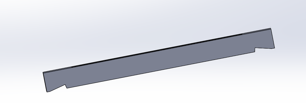
One comment on the clamping — for mechanical advantage you want the clamp to be elevated at the end which isn’t touching the workpiece and lowest where it touches the workpiece.
I’ve been playing with clamp shapes (super easy if you have a 3d printer). It’s not visible but the wider ones have ridges and I meant them explicitly for holding down the sacrificial ply but in general they should prevent lateral movement towards the clamp. The more traditional clamps that bridge between the two board have a notch so slightly more contact surface is in play and from above even when they’re angled up.
In this instance I didn’t go nuts because I’ve run this job like a dozen times with double stick tape and I only have once instance where it released a small piece early, so I was just supplementing that.
What I don’t understand is it’s leaving the marks all the way around. If it left them on the left/right I could assume it’s not square on x, or y if it were only on top and bottom. But this seems equal all the way around.
Edit: it’s less pronounced on the horizontal x only movements but that’s also face grain and I’d expect a better result. Either way if it’s tilted in one direction I’d expect a groove on one side and a ridge on the other. I hate to toss another bit, I guess I can try it slower but these settings were more concervative than gwizard wanted.


 To be honest from what I saw the ridges stuck out not in, which isn’t how I’d expect an endmill to bend if under pressure but doesn’t matter. Redoing a bunch of stuff to skip the finishing pass and just run as a normal cut and then will try it in maple again.
 . Also one tiny ridge you can see below on the left(bottom) piece on that first step down into the interior, but that was me having a .1 step down into a .125" deep hole, so now it will do that in one pass.