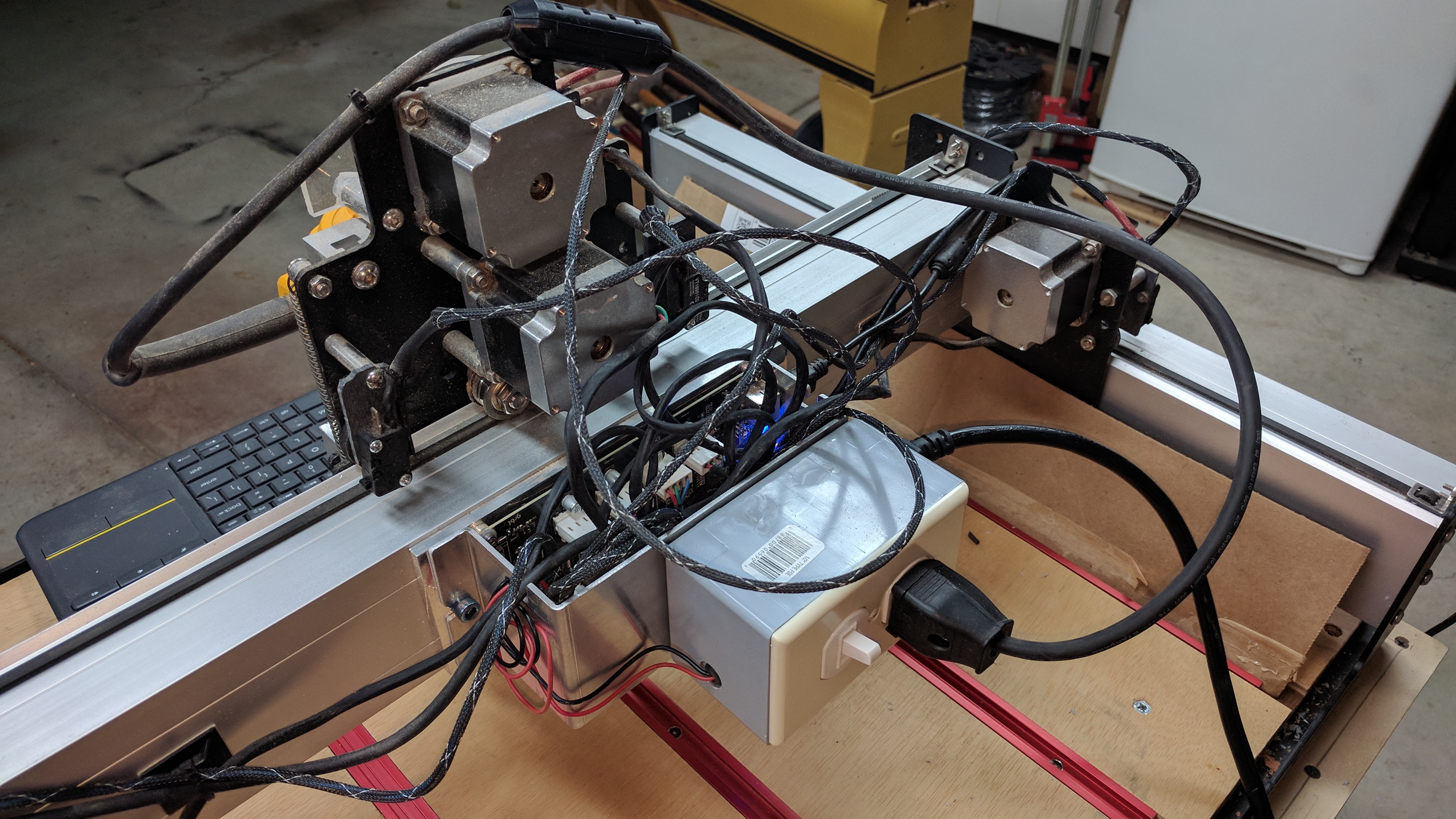
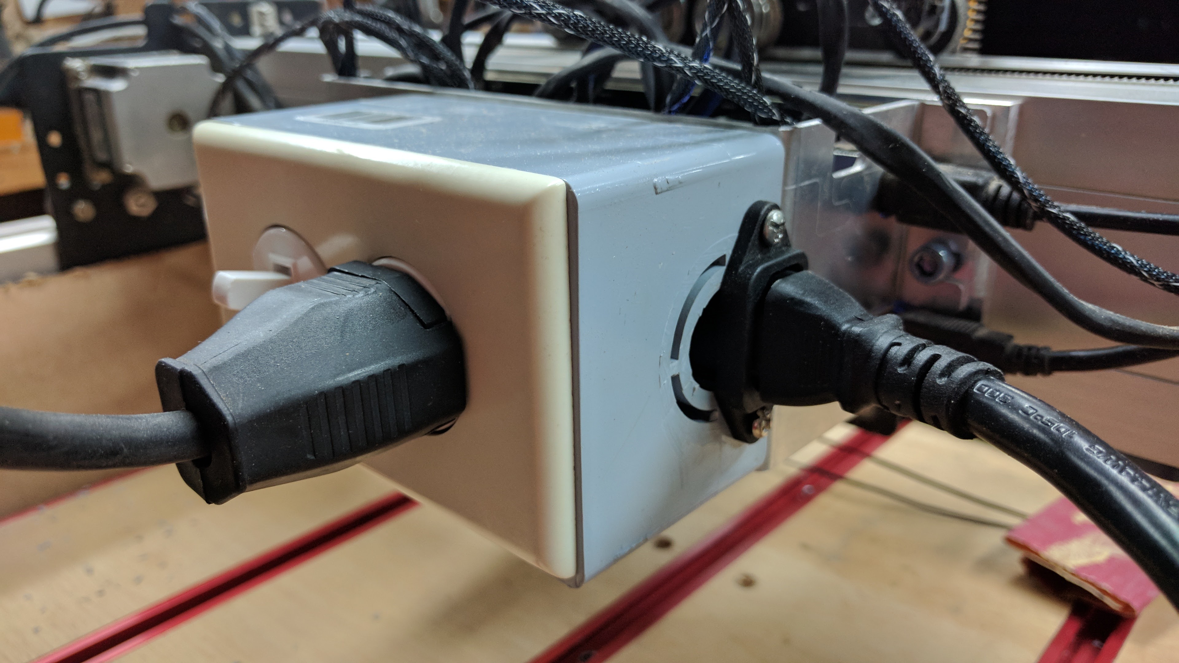
Thanks for this post. I’ve added this to my og SO3. I hid the relay inside an electrical box and added an IEC jack to the box too for the power input. I also found that the Vectric software adds an M3 command near the beginning of my programs and an M30 command at the end without me having to do any extra steps. The M30 seems to stop the spindle just fine.

3 Likes
I have done exactly as you have. The Dewalt router does indeed turn on and off. The problem I have is the router stutters and stumbles. Initially, I thought it was brushes going bad and I replaced them. I’ve checked that the relay is actually connecting both terminals.
I’ve tried a different relay, with the same results. Anyone have any ideas?
As if it’s not fully turning on/getting up to speed? I had that when using a water pump. If so that might be the relay - on your program set your speed to 10,000 rpm - that will output maximum voltage ensuring the relay is constantly on.
If that doesn’t fix it check your PWM connections
1 Like
Sorry for the late information here (been away). I’ve done this, and no it doesn’t work right. It leaves the spindle off until it gets to the initial tool set (as it would on the Nomad), brings the router to the front, turns on the spindle, then puts the dialog up. I’ve reported it for both CM3 and CM4, so I’m sure they know, but it’s not working right yet. There hasn’t been another release of CM since the last time I tried it.
What are you using to generate your gcode?
CC and Fusion 360. Both have the same result. The gcode is legit, with the commands in the right order (tool select then spindle on). Identical code works fine in the nomad.
Interesting… and this is all then sending through CM? Does it behave itself if you use something like UGS or grbl-panel? CM is becoming notorious for mucking about with the gcode before it sends it to grbl…
Given that CM actually manages the motion for the tool change, no, didn’t bother to try it - this is a case where CM mucking about with the gcode is clearly not working right. Before someone asks, using the IoT Relay (https://www.amazon.com/Iot-Relay-Enclosed-High-power-Raspberry/dp/B00WV7GMA2/ref=sr_1_1?ie=UTF8&qid=1508892584&sr=8-1&keywords=iot+relay) and it properly turns on when on, and off when off, this isn’t a plugged-into-the-wrong-socket problem. The only time I get spindle control in the wrong state is with a tool change (after acknowledging the tool change, the spindle then stays on, it doesn’t turn off then)
Thank you for the info. I do use the M3S10000 command. I did, however, find a cold solder joint on pin 6. That seems to have cured the problem, at least with no load. Again, thanks for the info.
2 Likes
Does setting the RPM fixed to 10000 to get the PWM to be 100% have an impact on other calculations in Carbide Create? Like are feeds and speeds changed if the actual RPM of the spindle is lower than the 10000 RPM entered in the software?
Not in the current implementation — once you begin to manually edit things, the program gives up the lead, and you’re in full control. Don’t know if this would change in a future implementation — maybe send in a feature request to support@carbide3d.com to afford a “turn spindle on” checkbox?
Ideally it would also let you know what RPM / dial setting one should set the router to (there’ve been a couple of times I’ve had to open up CC to check on that).
I thought that adding a peak detector (one resistor, diode, capacitor) between the PWM pin and the SSR could be a good idea to make the SSR switch on at any PWM setting other than 0. That way the correct RPM values could still be entered in the software that generates the G-code.
1 Like
That sounds like an excellent idea! I’ll look at putting something together… unless you want to throw together a quick logical wiring diagram?
I would suggest something like this:
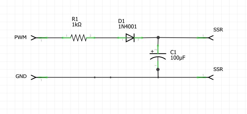
Not sure about the capacitor value though. That might be too little…![PeakDetectorSchematic|690x319]
1 Like
Nice work! Trick would be in sizing the resistor (which I think should be in parallel with the cap) such that when the pwm signal drops, the cap discharges fast enough for the relay to see no voltage. Unless you think the current draw from the relay itself would drain the cap sufficiently quickly?
The current draw of the relay should take care of that in no time. The resistor is mainly in there to protect the output of the controller board from the capacitor drawing a too high current in the first moment. The Arduino outputs are usually good for ~20mA, so we could get away with a 270 Ohm resistor but 1K seemed the safer option to me.
1 Like
One more question on the SSR, @Adam_Xett: How hot does the SSR get with your spindle? I was wondering if it would be sufficient to bolt it directly to one of the Y-axis extrusions and use the extrusion as heat sink?
My spindle is a 1050W, 240V Kress, so with ~5A even a little lower current than the 6.5A Makita mentioned on the Wiki page.
@reibuehl I’m using the SSR with a Makita at the moment (Spindle in the mail). I have it bolted directly to my rail with a bit of heat compound (diaper cream) and it never breaks room temperature. I did some testing running my shopvac (far higher current draw) through it and when connected to the rail it just barely got warm. I think you’ll be just fine with a 5A draw.
2 Likes
I think there is potential here for an aftermarket kit!
I agree  and it is on my radar. I’ve got a VFD and spindle coming in the mail shortly and I’m going to do a separate write-up on Spindle + Speed control for the S3 once I have it.
2 Likes