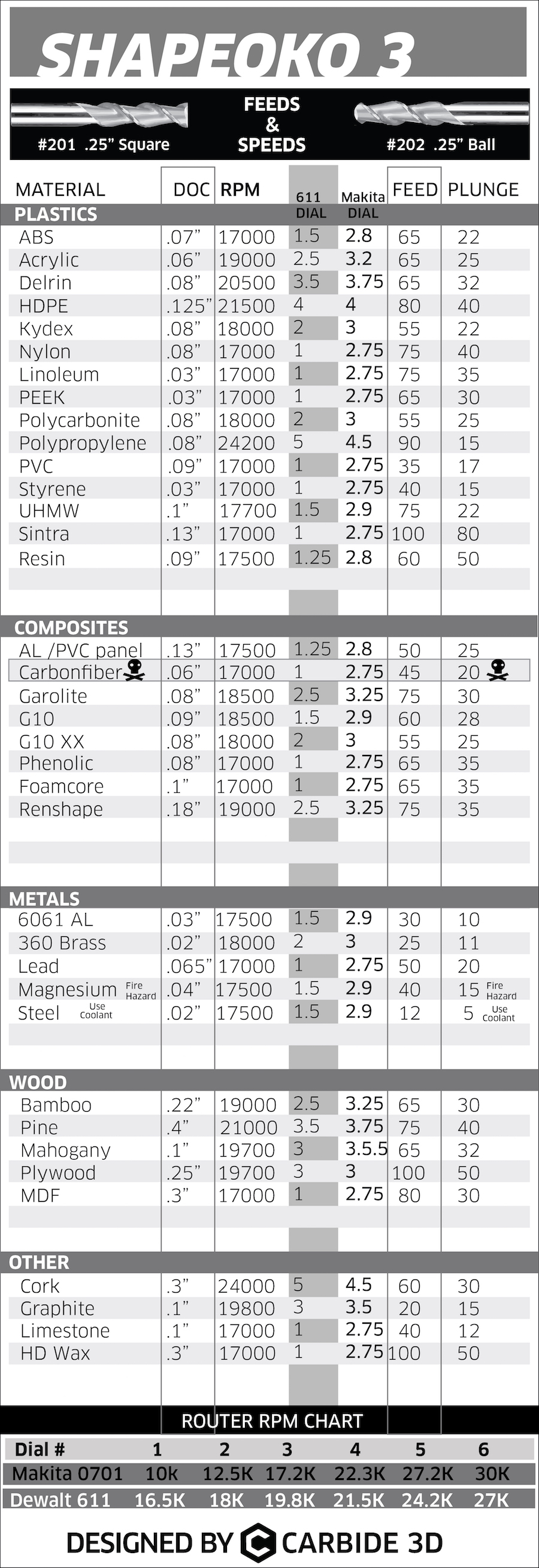
Ok, that makes sense that the S3 needs a more conservative chip load. But, is there a formula to take the known chip load from 1/4" and figure out the 1/8" settings needed?
It looks like the pdsspindles chart roughly lists the 1/8" chipload as around a third of the 1/4" chipload. Do you think simply dividing the feed rate by 3 (so, ~27) and keeping the RPM the same a good way to start?
No, as I understand it, to reduce chipload you would reduce RPM (but that’s wrong? see below) — managed to melt a glob of HDPE onto a 1/8" endmill not thinking about that and using the 1/4" feeds and speeds.
We do have one pair of data points for 1/8 vice 1/4:
Aluminum
1/8″
Depth: 0.762 mm
Speed: 17250 RPM
Feed: 762mm/min
Plunge: 254mm/min
vice
1/4″ #201 or #202
Depth: 0.76 mm
Speed: 17500
Feed: 762
Plunge: 254
Hmm, never noticed that they are essentially the same. I’ll have to dig out my notes on the 1/8″ cutting — used the same file, so pretty sure I just reduced the RPM.
@ApolloCrowe any possibility of resolving all this and getting an official feed / speed chart to support Carbide 3D selling the 1/8″ precision collet for the Dewalt?
FWIW, I’ve always wanted to see a CAM feed rate tool which was dynamic and physics-based, and which could adjust spindle RPM on the fly for machines such as the Nomad, calculating material remaining with each spindle revolution, dimensions and heat load of each estimated chip, based on the content of a G-code file.
Obviously need to research and work up a basic understanding of this ex nihilo. Here’s a start:
The formula to calculate your chipload is: Feedrate / (RPM × # of flutes). To increase chipload: increase feedrate, decrease RPM, change to an endmill with fewer flutes. To decrease: decrease feedrate, increase RPM, change to an endmill with more flutes.*
After reading a little more, I feel like we’re skipping a big step of not getting the cutting force figured out first. Accuracy, speed, and prevention of broken endmills are more important to me than chipload (which is just wear reduction, right?). I feel like having a formula that takes in janka hardness and a desired chipload could be enough to get decent settings, but I’m over my head at this point as to what that formula would be and the S3 datapoints to support it.
Back to chipload: since a lot of the settings for the 611 are already at dial 1, reducing RPMs isn’t an option on many materials.
BTW, could you add an “or” to that definition, i.e., “increase feedrate, decrease RPM, or change to an endmill with fewer flutes”?
Yeah, calculating the cutting forces should be a factor in this — if they get to a point where they’re significant — I had a belt slip while cutting Ipê and the machine powered through a full 1 inch depth cut just fine.
Arguably we should all just get a copy of G-wizard — though I was a bit taken aback by this note on the Shapeoko settings in it:
More germane to our current discussion here, /u/aboqsa went on to say:
Related to 1/4" → 1/8" mills. I’ve had this issue a lot too. Probably the most important thing I’ve noticed is that the step down in chip load from 3/4" to 1/2" to 1/4" is fairly linear. However, 1/4" to 1/8" is roughly double the step down. I assume this is because mill deflection is finally becoming a serious factor.
The note on reddit isn’t -totally- wrong. It seems to take a little black magic to hit the exact right setting, but I haven’t had G-Wizard give me anything just crazy. To the posters point, 16K -IS- too fast, and the software is basically telling you that the cut you want isn’t possible to do well with the tool and other settings you’ve chosen. That’s not wrong, but it could be more clear.
If you’re really trying to avoid broken endmills, g-wizard provides some good input. Far better than you can get from just guessing. The Carbide speed+feed chard is a good starting point, and matches up well with a few spots that I’ve checked against g-wizard, and g-wizard had dramatically dropped the number of broken and chipped endmills I’ve produced
Honestly, after putting well over $1000 into the cnc mill, spending $80 (it goes on sale pretty often, just keep an eye out) is a cheap investment in reducing tool breakage. It is a weird tool, could use some UI design, could be a lot friendlier, has a steeper learning curve than it needs, and isn’t very well documented for the newcomer… but all that said it’s still the best tool I’ve found that I’m willing to pay for.
There -are- free tools on the web for calculating speeds and feeds, I think they’re in the SO Wiki (Will points to these all the time, so I’ll just skip it)
Yeah, the thing is, I’m still stuck in the project’s original opensource roots — I use Carbide Create/Motion and am learning MeshCAM 'cause they’re “free”, but I’d be much happier with opensource, if for no other reason than I just don’t want to go through what I’m currently going through w/ Freehand for any other software (hanging back on 10.6.8 for Mac OS X, fretting with each patch / upgrade that the app will quit working on Windows).
And, I’d like to understand all this well enough that I would be able to make effective use of G-Wizard if I chose to get it.
There’s a new thread on this here:
and I’m going to continue all this there, since we’re getting away from the official charts.
I guess what I need is a chart that is comprehensive to all of the C3D endmills.
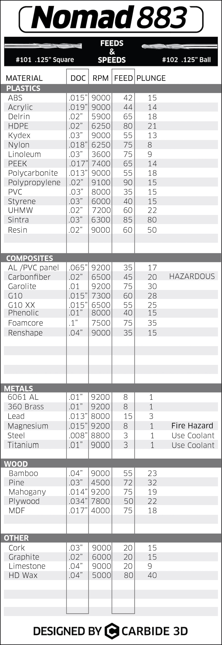
What I need is recommended feeds/speeds for #112 the .032" endmill. I have 1 left out of 3 as I broke the other two… Using a Dewalt my minimum is 16k spindle speed so I am a bit limited. Carbide Create shows the spindle speed to be ~5k. Make sense?
Sorry to be a bother. When I first looked at this post it didn’t show the whole thread which is why I asked. When I had clicked that first link I still couldn’t find it. So after I posted a reply voila, the whole thread appeared and I found the charts in question.
Doing some testing in pine using a 1/8" endmill has finally worked its way up to the top of my priority stack, and is what’s scheduled for this evening (then HDPE, then some tropical hardwoods) — so hopefully we can have some hard data presently.
Still trying to find an opensource spreadsheet / calculation system I like — pyspread hasn’t worked out as well as I was hoping, and the spreadsheet component for the jupyter notebook system has me baffled.
Haha sounds like the story of my life! I have worked in IT since 2003 and currently run my own business so I totally understand. If there is anything I can do to help on my end I would be glad to where I can.
When it comes to this CNC stuff I am still a total noob. What I was trying to do is cut out a small image like this photo shows
The only problem is I wanted the cutouts to be inside a 140mm x 140mm square so naturally, I would need to use the smallest bit I have. But I will be patient as I am getting comfortable enough in using the larger bits in the sheet metal with my coated #102-Z and #201-Z.
My inclination for something that small and detailed would be to start w/ a V-carve, then finish up with the small endmill if needed — I did that for my locking register calipers: https://www.shapeoko.com/projects/project.php?id=154 and the additional detailing was nice.
Hey sorry. I am using Aluminum 3003 grade. I will be switching to 5052 or possibly 6061. My provider said 5052 is the hardest while still allowing bending. Not sure if it matters when my stock is only .04" thick but I know 3003 gets gummy and I am really looking forward to not using that anymore.
I just tried creating a 2D contour with the V-carve bit and it churned out even more errors. I know I will eventually figure it out but I am still stuck with nothing.
Ok I am an idiot… Instead of doing a 2D contour I changed it to a 2D engrave using the chamfer and the simulation completed. Now comes the cut test!.. Sorry I am an idiot haha

 I have worked in IT since 2003 and currently run my own business so I totally understand. If there is anything I can do to help on my end I would be glad to where I can.