Simple First Project

Here is another box tutorial I made to share with anyone looking for an easy project to run on their machine.

I used 3/8" (9mm) baltic birch and finished it with English Chestnut stain, then a clearcoat to seal it in. After making this project I’m really thinking about making a bunch of these to store all of my random supplies in. Adding text to any of the faces (to help identify the box) woudl be trivial and a nice way to keep everything organized.

Here’s a link to the project, including design file and gcode: http://docs.carbide3d.com/tutorials/project-simplebox/

-Edward

10 Likes

cough Carbide Create Wizards cough

1 Like

cough cough we’re on it cough cough :+1:

3 Likes

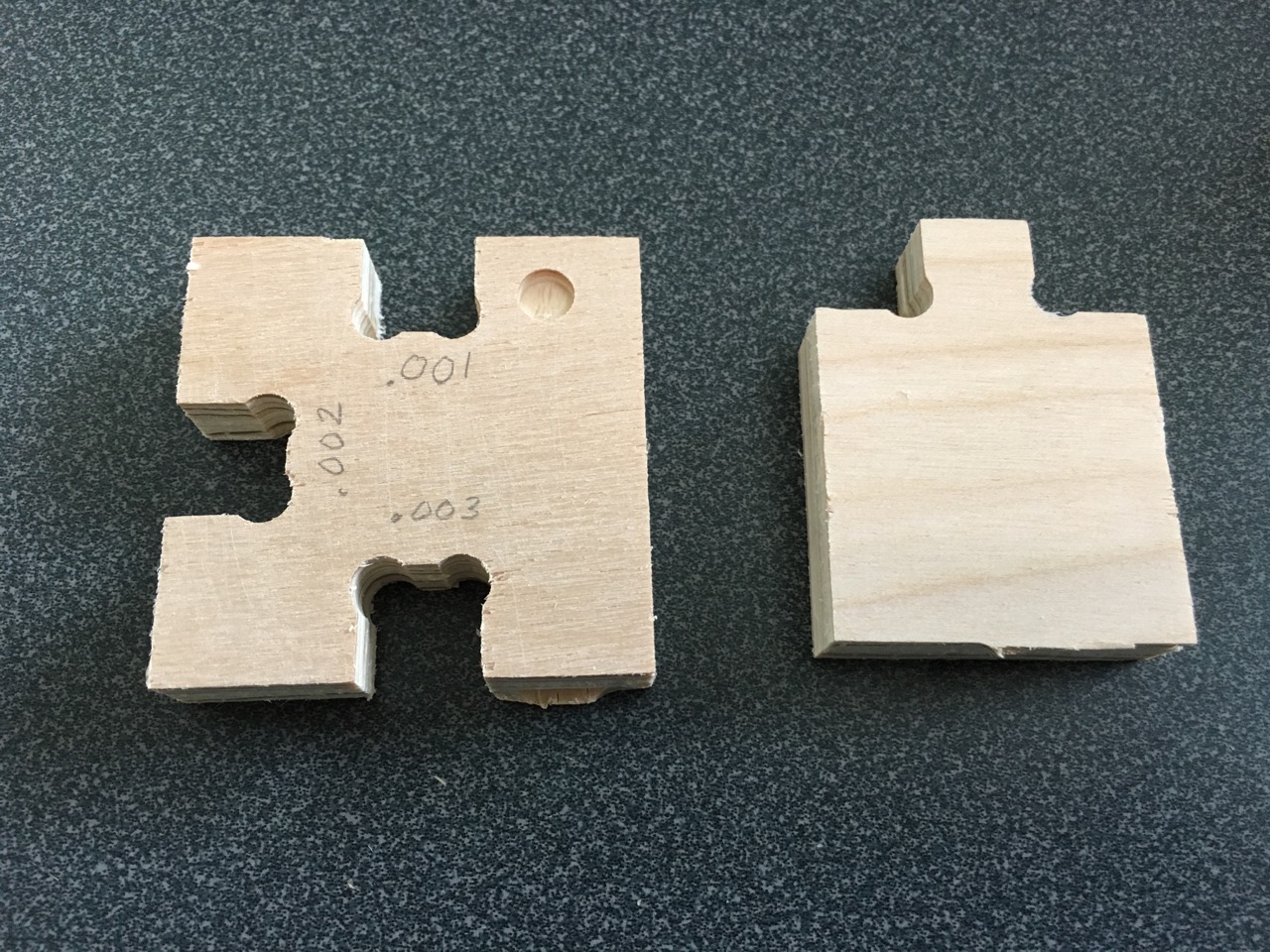
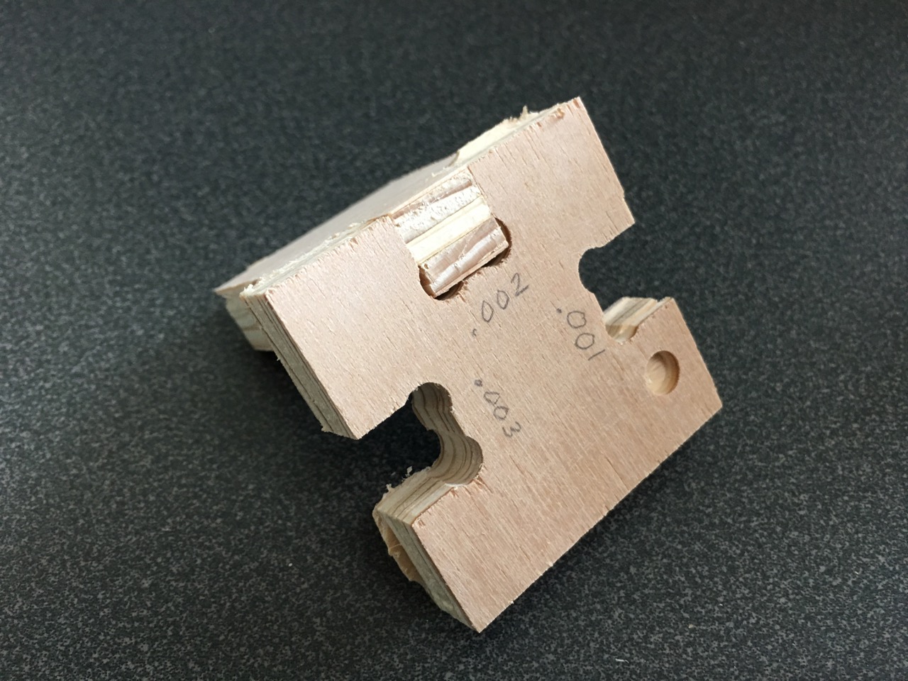
I thought I might try creating some of these joints so experimented with clearances. A .002" clearance (slot .004" wider than the tab) gives me a nice tight fit that can probably be used without glue. A .003" clearance is a nice slip fit with room for glue. How does that line up with your design?

1 Like

This project was recently mentioned on Facebook, where two issues came to the fore:

  • the person who mentioned it failed to realize the importance of the stock thickness
  • the .c2d file was created in a version far enough back that it does not open properly in current builds

If you download the file in question and open it in a current version of Carbide Create one gets:

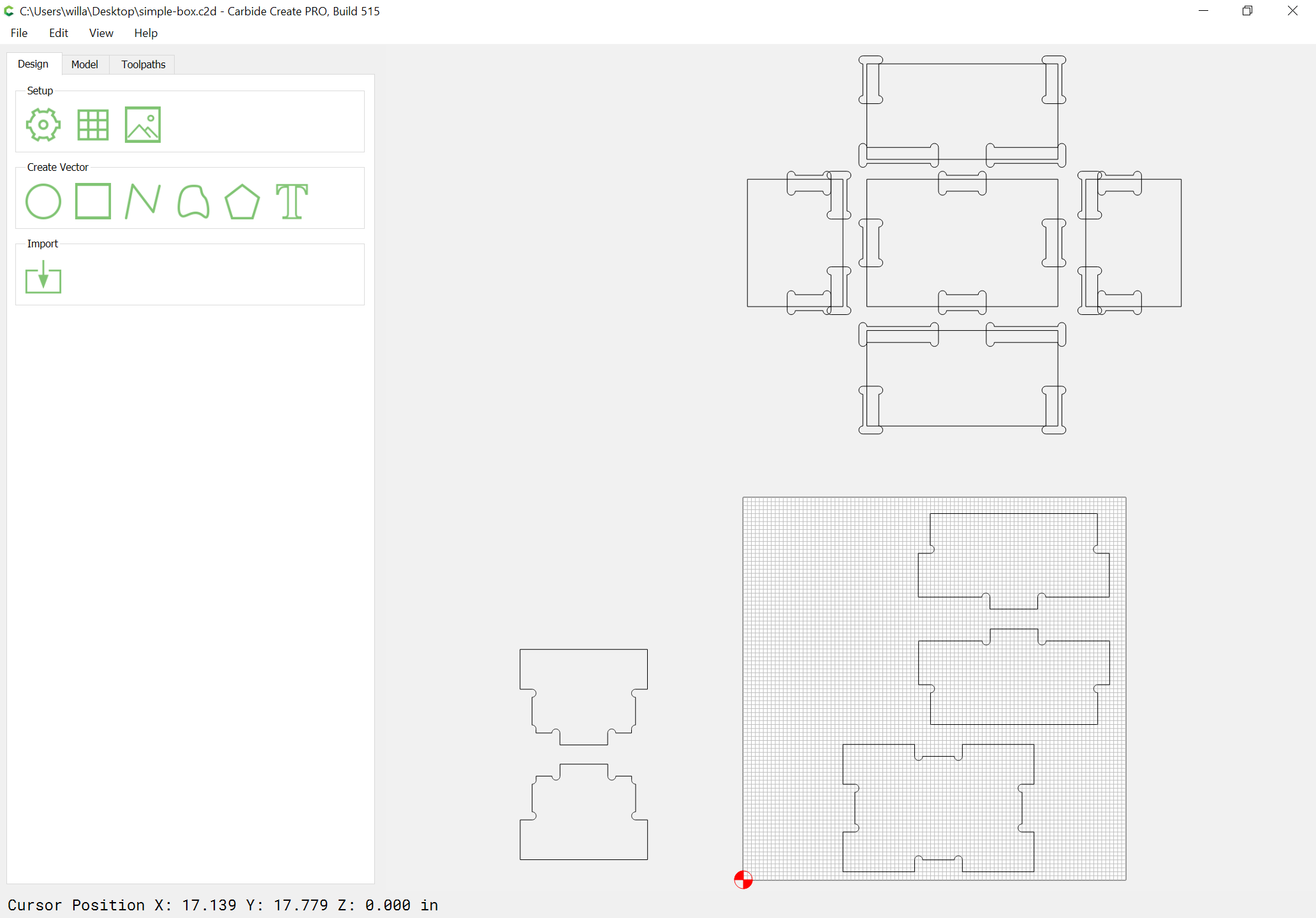
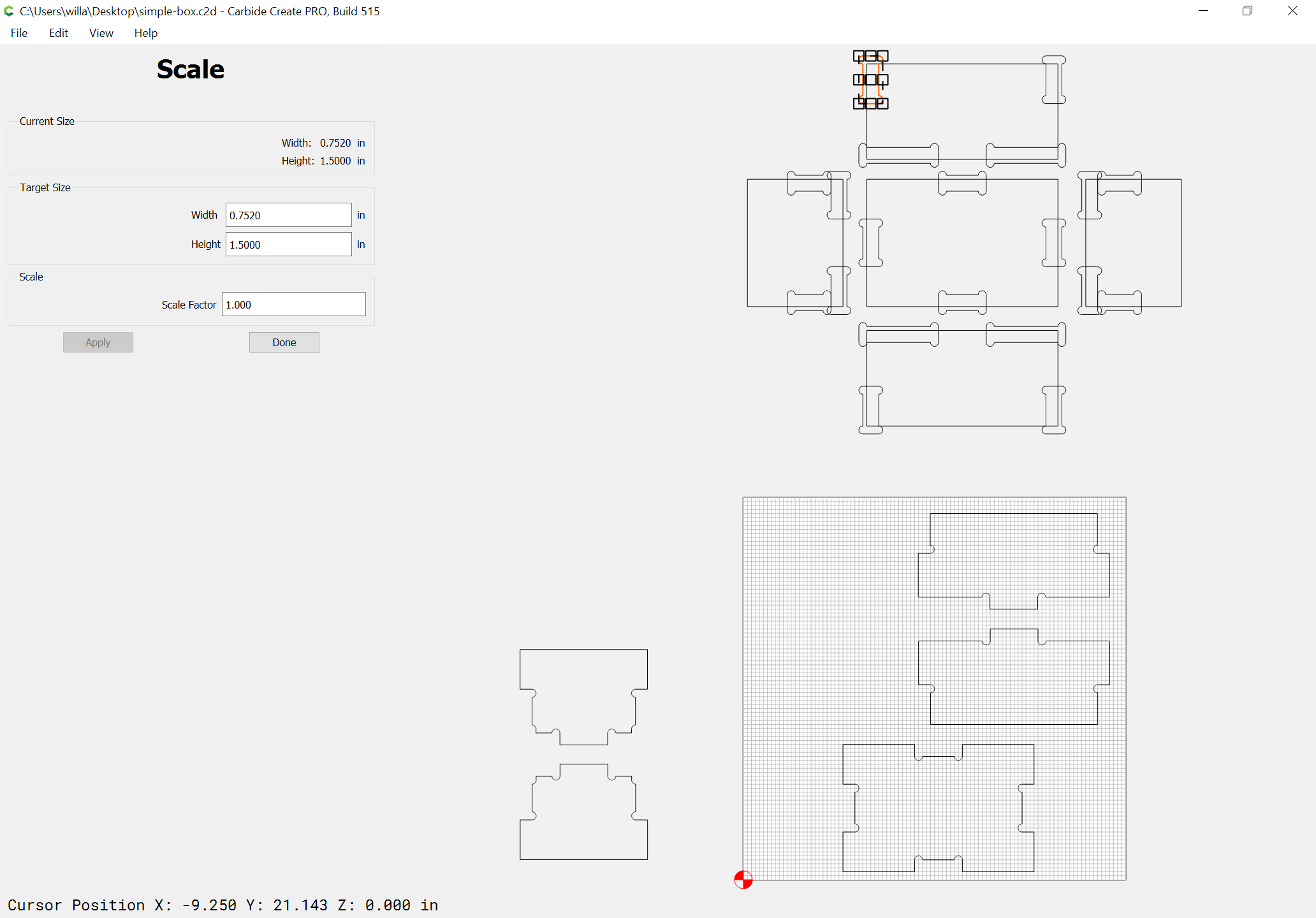
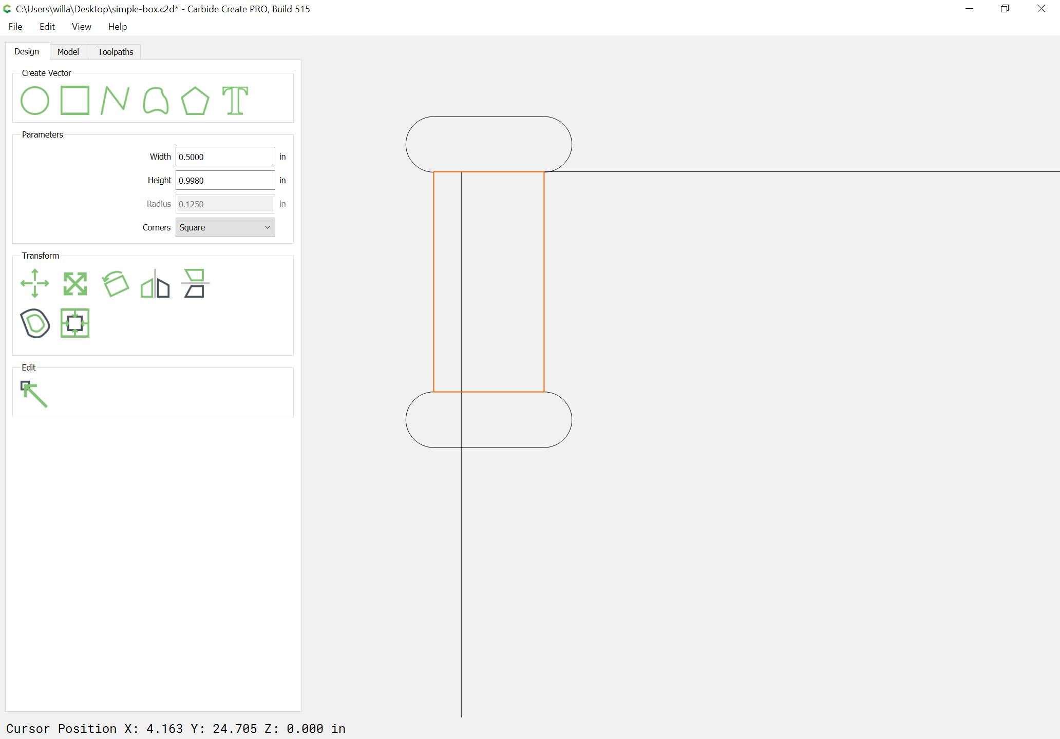
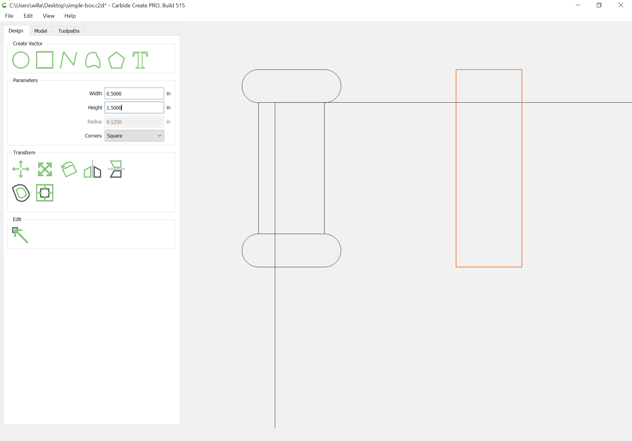
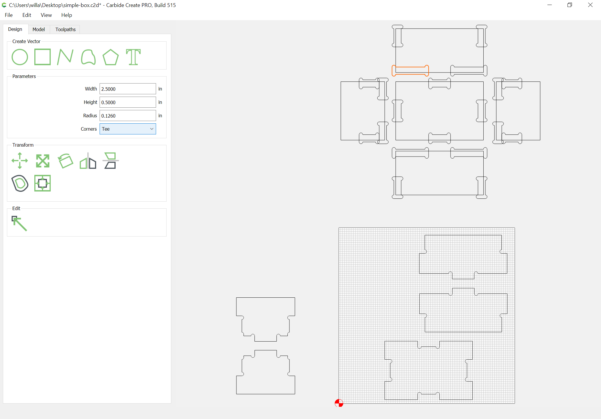
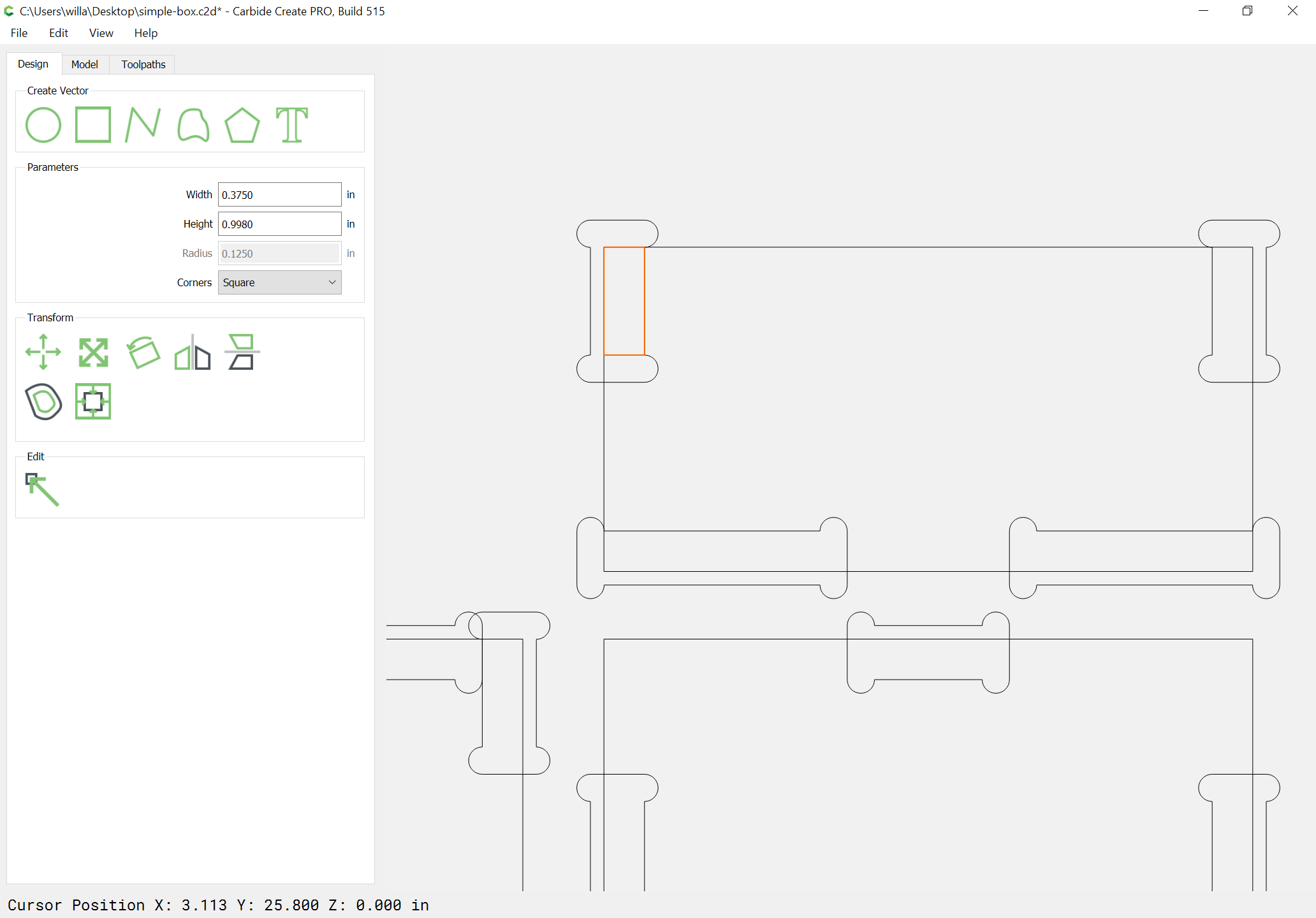
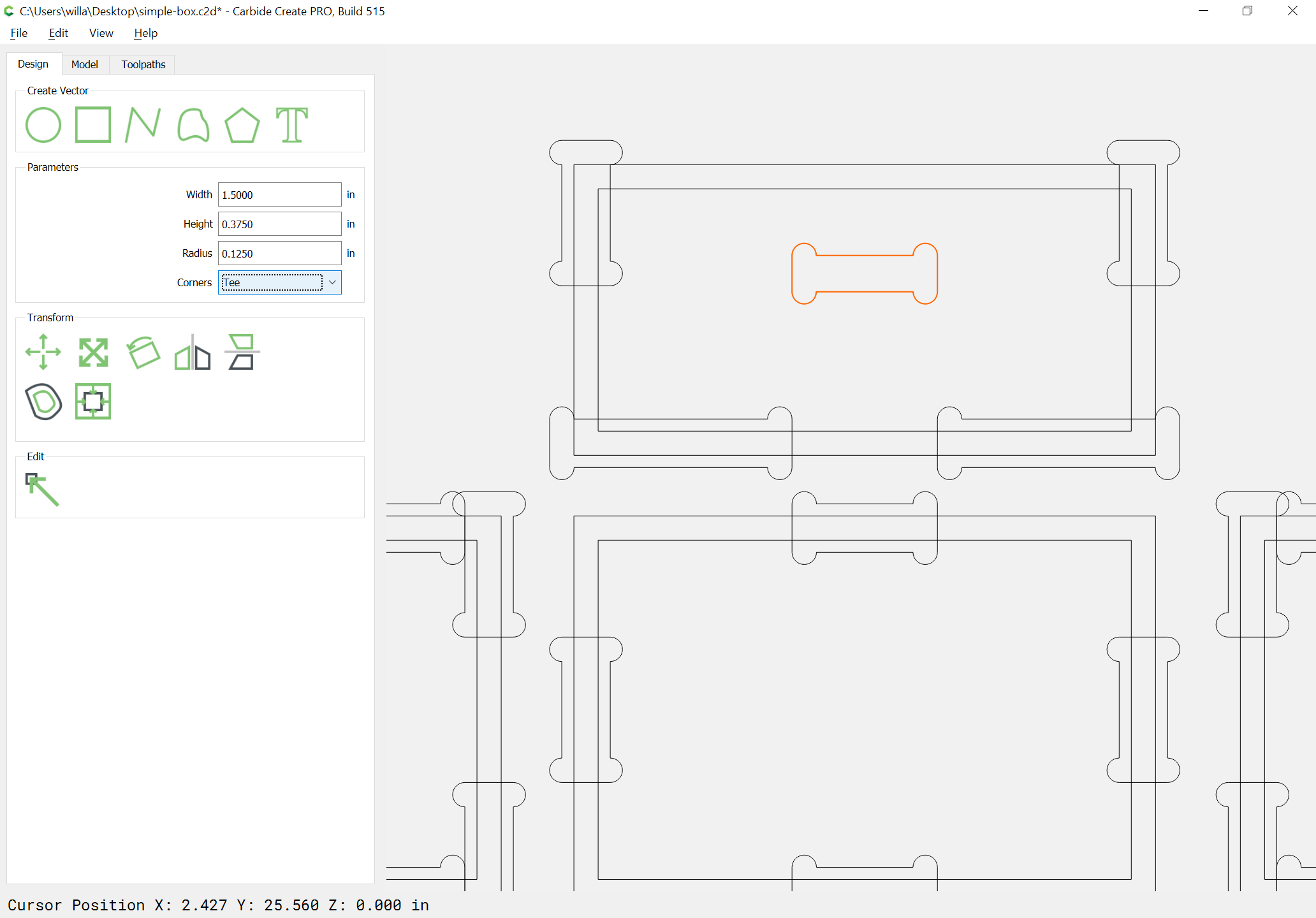
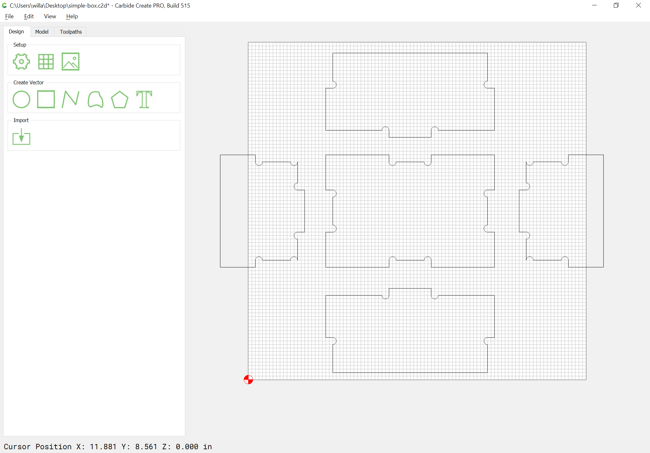
Selecting one of the tab cutouts, we find that it is geometry, not a rectangle with parameters which may be updated, so we need to recreate each such rectangle to allow for simple size adjustments:

Selecting the Resize tool allows us to ascertain the dimensions of a given tab:

It is necessary to draw in a rectangle to verify the size of the dogbone cutout sans the dogbone/tee structures:

with the two necessary dimensions, we can draw in the desired rectangle at the appropriate size:

and then add the tee (T) extensions:

which shows that we need a slight adjustment in orientation:

With that adjustment made, we can rotate the cutout to get it into the desired orientation:

Interestingly, the rectangle loses its rectangle nature, and changing parameters ceases to be possible.

And it turns out that the unrotated instances, are still rectangles:

If we draw in a rectangle we can verify the thickness of stock which the joinery is set up for:

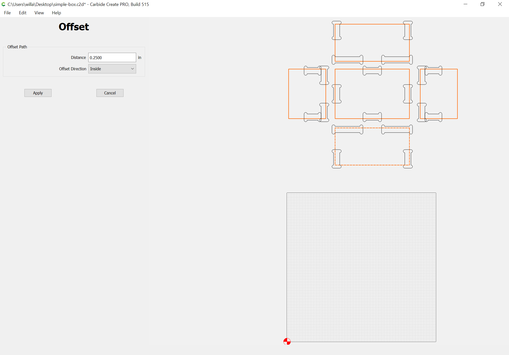
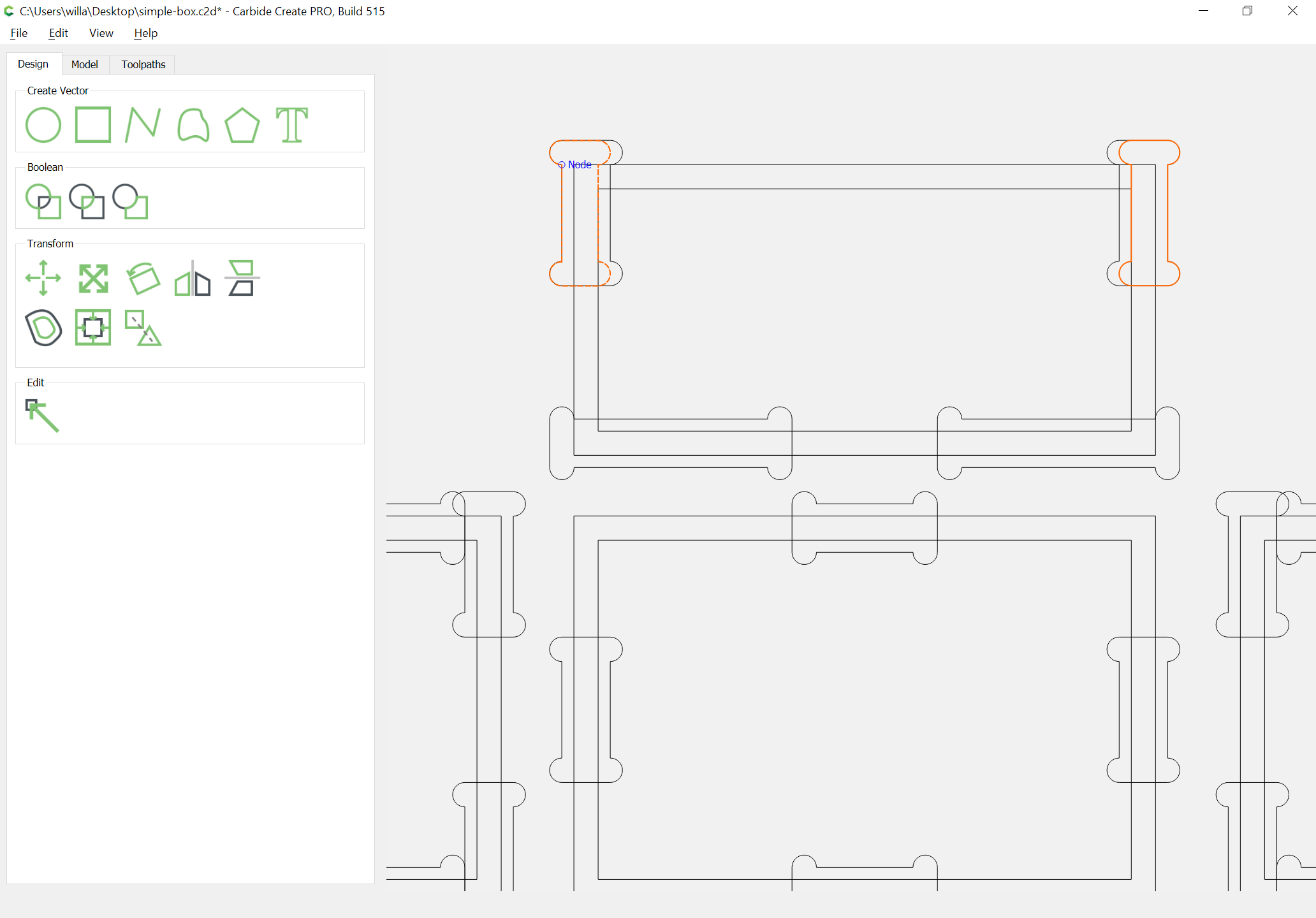
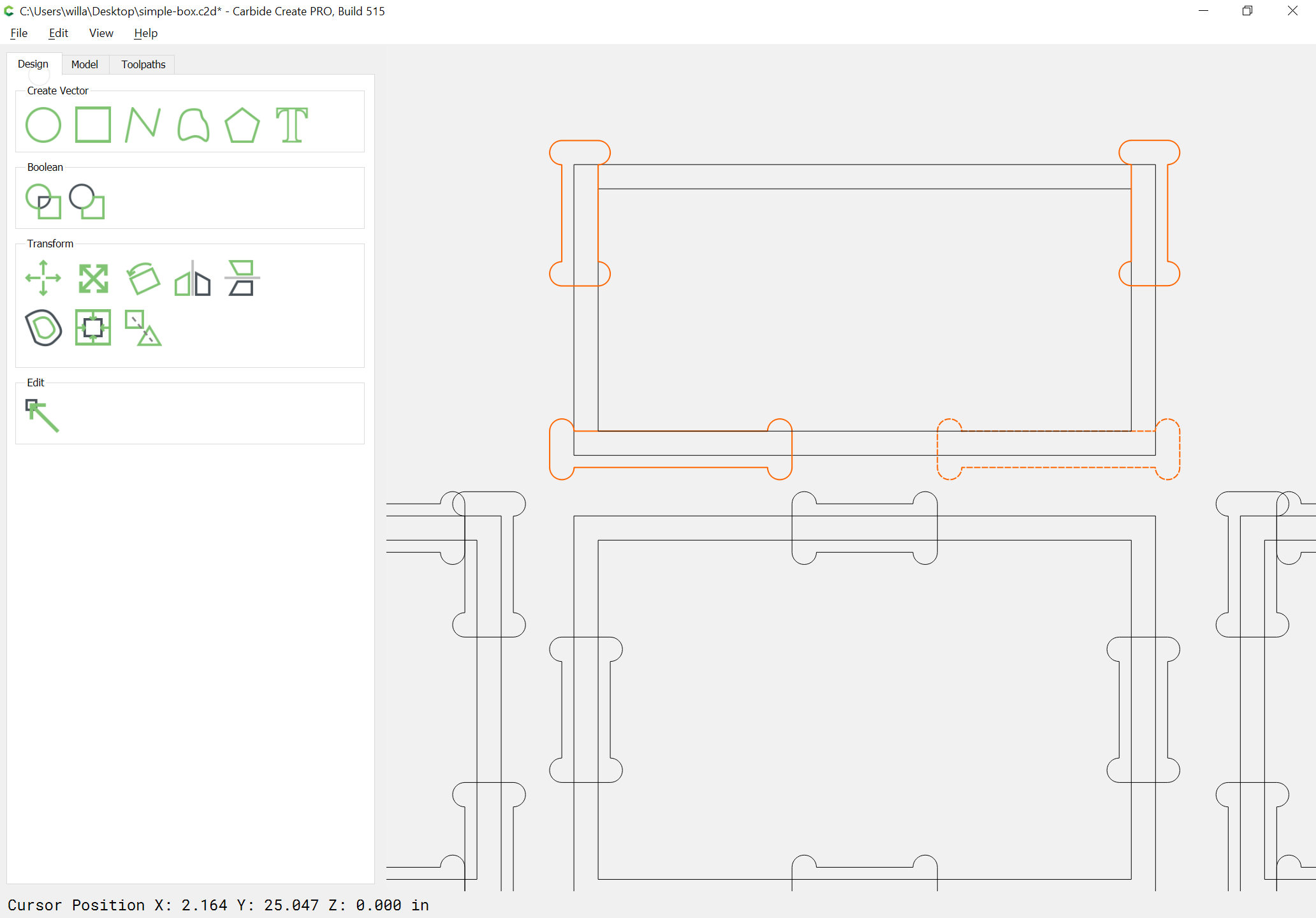
Changing the thickness of stock can be envisioned by selecting each rectangle which represents the parts and insetting it by the desired stock thickness:

So we create teed rectangles which are the appropriate size:

and rotate and drag them into position:

and repeat this process for each other:

It will be necessary to adjust the middle tab at least for the change in joint dimensions caused by the altered stock thickness:

the area in-between the two rectangles needs to be added to the joinery:

Then it is simply a matter of duplication, rotation, mirroring, and dragging into alignment, then deleting the original/unnecessary geometry:

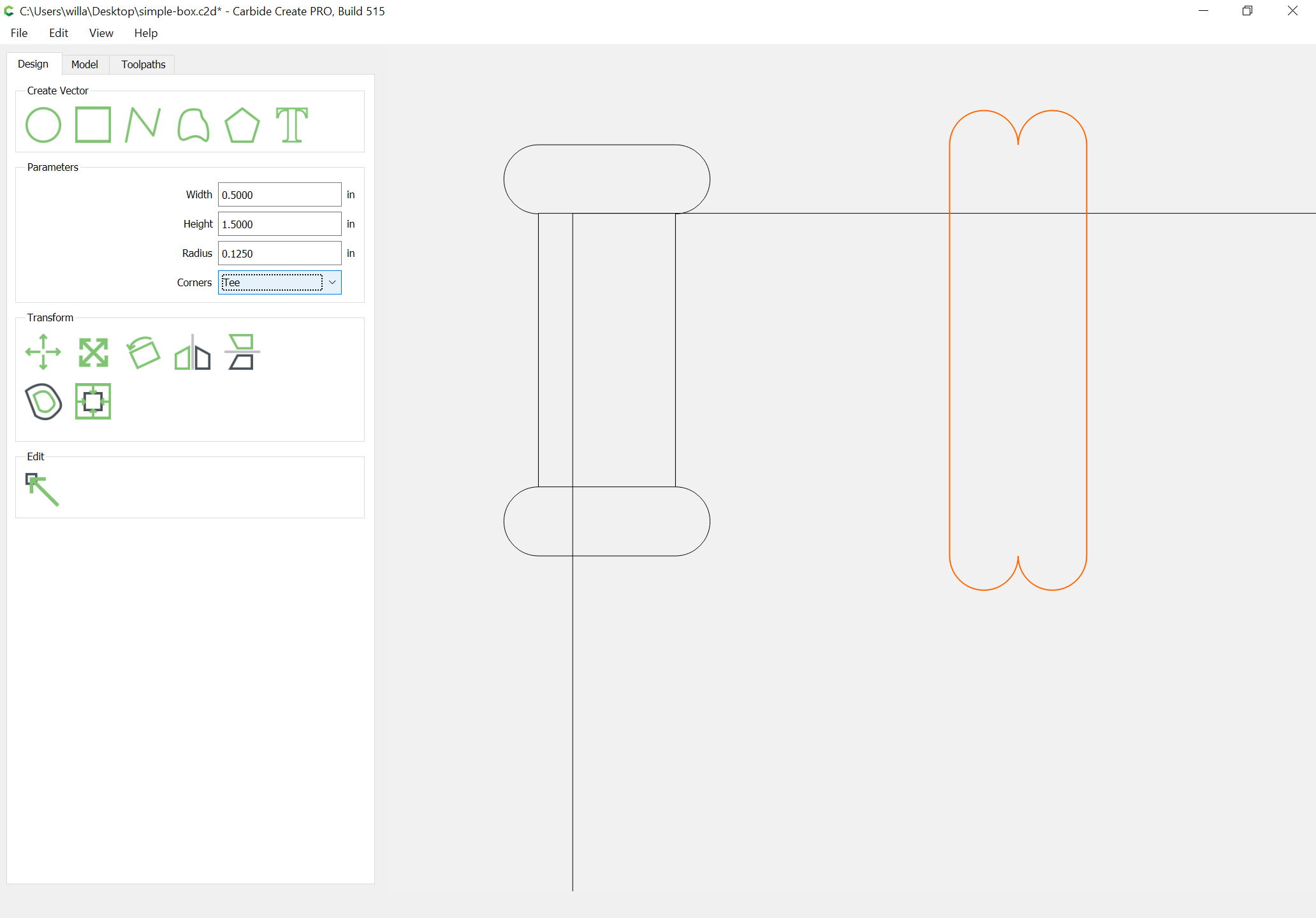
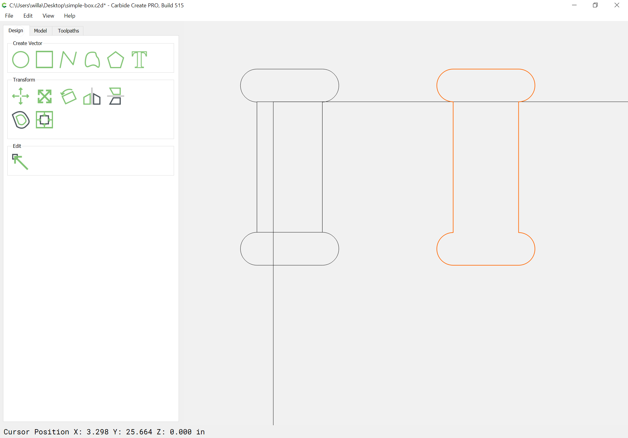
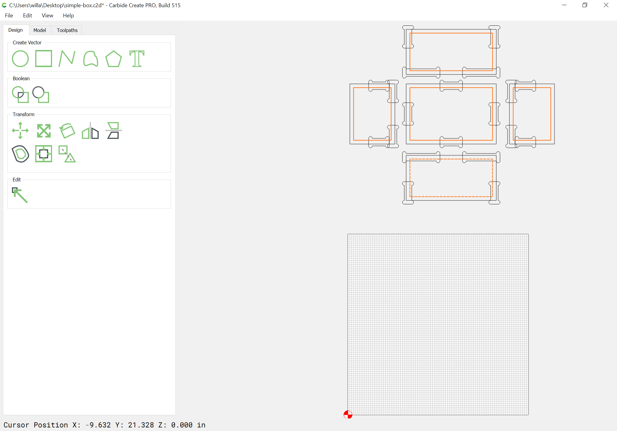
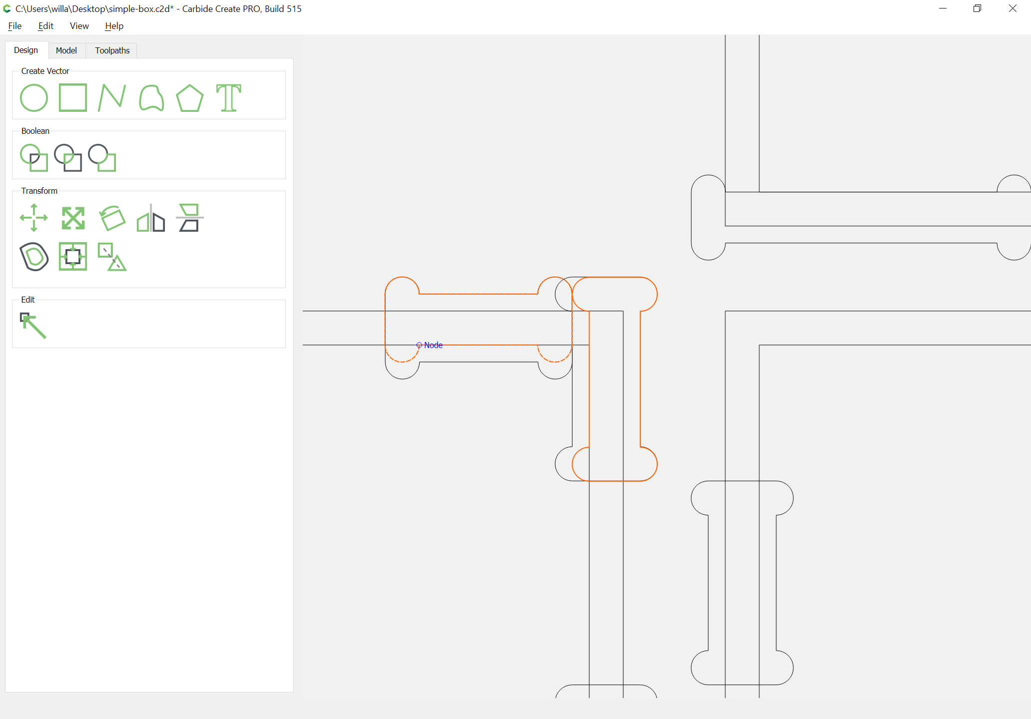
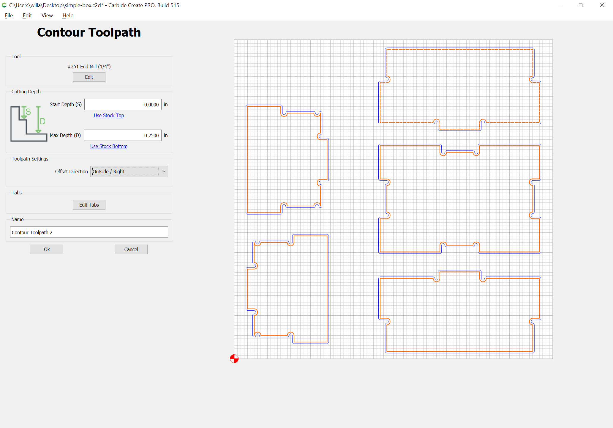
Then duplicate everything and drag it to the working area, select a part outline, and then shift click on a tab/dogbone outline so that it is the key object and Boolean subtract:

Repeat that for each:

Then drag the parts into a suitable arrangement and apply Toolpaths:

and if need be add tabs.

Attached.

simple-box_one-quarterinchstock.c2d (747.2 KB)

3 Likes