The job I did which made it super easy to see the issue with is here:
Roughing pass only
Waterline pass only
It’s a super simple model: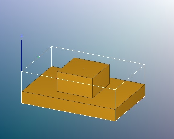
and it’s sized for the 3x2x1 blocks of renshape and wax we got with the machine.
You can see what the stepping errors resulted in in my earlier post here.
Also, if you have the same problem that Randy and I had, you can just run the first program in the air without actually milling away any material and you can even hear the glitches in the stepper motors as it runs. The glitch was manifesting itself apparently as the motors taking too many steps every once in a while, so you can hear the motor, while the mill should be going in a straight line at a consistent speed, occasionally go up in pitch for the tiniest fraction of a second.