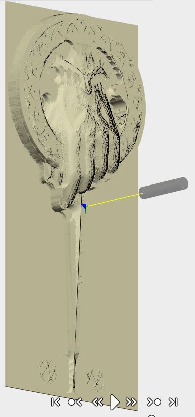
Does anyone have a good tutorial of taking an STL and turning it into something that can be milled in Fusion? I’ve tried several different tutorials, but my limited fusion and STL knowledge seems to be a barrier. I’d like to make the pin below.
I’m interested in how people are able to set up cam operations once they bring the STL into fusion. I’ve seen lots of info on converting to brep, but even when I do, I don’t know to properly set up a cam operation. It breaks it into 13000 triangles, and I can’t create a contour.
You may be over-thinking it and making it too complicated. I was hesitant to do a 3d thing until I watched one of Lars Christensen’s videos on 3D. His basic advice was to choose a strategy and make no changes other than the tool. Just see what it does. F360 does a reasonably reasonable job of figuring out what you want to do. Here’s a Fusion 360 link to a fan I did for the DeWalt. I downloaded an STL, imported it into F360, converted it to a brep and then started doing some changes, such as adding the collet “socket” and making the outside a little thicker. When I went into CAM, I chose some stuff and watched it in the simulator. The tools seem to understand what you want to do without you having to do anything really fancy. Any way, maybe looking at the link will help some. http://a360.co/2uDDyAf
I took a look at your fan, and it has some pretty easily seen contours that the program needs to follow. The file I supplied (above) opens with a billion triangles, and I can’t seem to select a contour to cut the piece out, or a contour to just cut the top profile. Did you need to somehow join the triangles on flat faces (like the back of my pin)?
The fan was a small image and did not have that great of a mesh count. You could reduce the mesh in the Mesh menu, but that would cost you detail. Maybe Artcam is better for this. But I would post it on the F360 forum. The Autodesk people are phenomenal about answering questions and demonstration how something should be done.
I spent a little more time with this. First problem I had was importing it in at a reasonable size. F360 doesn’t know if it’s in inches, mm, etc and this info isn’t encoded apparently into the file. F360 also defaults to cm for things like this. So I imported the mesh and went into the Mesh menu to reduce the density so F360 would quit bitching about the size (.20 seemed to work). Then I converted to BREP. I immediately went to CAM, flipped to the backside, realigned the Z axis, selected 3D adaptive clearing, selected a 1/8 inch flat end mill and clicked okay and then went to the sim. Note: I took Lars’ advice for 3D and made no adjustments to the adaptive clearing. I just picked the tool and clicked okay and let it figure everything out. According to the simulation, that gives me a flat backside. I then went back to the front size and did the same thing with 3d adaptive. See what happens without selecting any contours or changing anything. Once you get the feel of it, you can start trying other finishings and adjusting the settings. Lars’ point was to see how the defaults work first. By the way, This is just from using the defaults and letting it choose the contours.A lot more time would be needed to see if it could be made acceptable/good.
@baaja@Boothecus
Have you seen Kiri:Moto?
I haven’t used much, but it’s a pretty slick basic tool that seems like it might work for these cases. I noted some issues to the developer a while back and he is pretty responsive. Not a full featured CAM tool, but I’m impressed. I’d love to see a result if you give it a try.
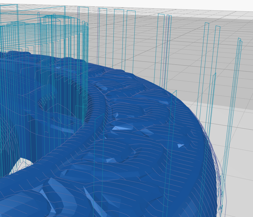
Added a pic of a closeup showing the toolpath on your model (I just clicked around):
You can run 3d toolpaths directly on STL files in fusion.
As for contouring unfortunately I haven’t found a great way as only the 3d toolpaths can be ran against an STL. You can make an object that follows the contour of the STL and run 2d operations on the solid body.
Thanks for looking at this! It seems like that route would take a lot to get the finish I would want. I’ve tried using remix to reduce the mesh as well and that seemed to make it worse.