The Carbide 3D touch plate is wonderfully precise, and the test LED helps prevent one from driving an endmill at full speed into it.
It’s especially nice for multiple setups for jobs — I did a flip job once where I routed and L-shaped pocket (to fit the touch plate on one side, then used the touch plate to register off that origin after the flip — lined up essentially perfectly.
I use an L shaped fence,(removable) in my lower left corner, so technically I wouldn’t have to rezero my x and y each time ( I do because it is easy) and have used the old school method of a strip of paper, due to the scarcity of the shapeoko probe. The advantage of the electronic probe is you get incredible accuracy whereas paper my be .004 thick. the probing macro in Carbide motion 4, makes 3 axis probing as simple as pushing one button.
All I can say is you cannot be as accurate as the touch plate. I’ve used a spindle mounted laser in the past for x and y axis zeroing which worked pretty well but not as good as the touch probe and it was significantly more time consuming then the probe.
If I understand you correctly, you are wondering why that level of precision is needed for x and y, when the material not precisely located or oriented.
For some things, you don’t care. If you are using roughly sized material and all the cutting is done with a single fixturing and tool, everything will be fine relative to itself.
If, on the other hand, you have no tool probe and change tools, the probe can be used in place of the tool probe and lets you set Z to match the part (or another reference)
The real use comes when you are working with material that is already sized (such as engraving or pocketing an otherwise finished piece) and you need the features to match, or you are doing a part that requires re-mounting, say to get the back side, or cut features in the side relative to the original fixturing. The touch plate lets you get pretty much dead on to the part. This lets features from several remountings match to the precision of the machine.
It can be used to check square by probing on two corners, as well as position.
If I generated a file in Create - a square, let’s say, whose bottom edge is parallel to the bottom of the work area - but loaded my stock out of parallel on my machine, does probing in X and Y orientate the program to the stock?
I will likely have some engraving to do, where I would like to make sure the part to be engraved is in the right location before running the program. For my first attempt, I machined a pocket in a waste board, inserted the part then ran the engrave program. If I could just bang the part down with tape in any location then probe to account for misalignment I can see it being VERY useful.
Yes, if you make a fixture which has a way to set its origin (usually I just design them so that they match up with one of the rapid position points) then the milled features of the fixture should be in registration / alignment.
-NO- it does not rotate the program to match. It assumes the material is parallel to the axis’, and only locates the corner based on that. If the material is not square to the machine, it will mis-locate that corner.
I believe so. It could be done, and it’s simple math (you need to probe each side twice, and two parallel sides) - if you were to do so, you would also be able to skip the need for knowing what the end mill diameter was (you could calculate it), as well as automatically calibrate the machine for belt stretch if you did know the end mill diameter.
To calibrate:
If you have a known pin in the spindle (P diameter) (an endmill with flutes won’t work)
And a known touch plate (W wide), and it is aligned with an axis (easy).
Touch the left, note the position, touch right, note the position. The width you will get is W+P. If it’s not, change the calibration in that direction. You can do the same thing in the 90 degree direction.
I think this should be built into CM, it’s fast, it’s easy, and if you have the probe, “should just work” and solve a lot of the problems people have with doing this. It requires -a- known size probe, not necessarily the fancy carbide active one.
To find alignment is more involved, but could be all automatic:
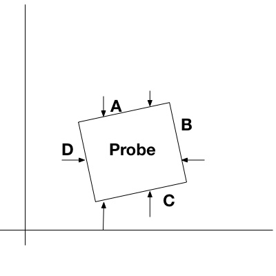
If you probe at the “B” end of A and the “D” end of A, you can now determine
The alignment of the A side to the axis. (because you made a square probe, you also know The B, C, and D alignment) . Probe the D and B sides. You can now adjust the program to align with the block, and properly find the corner of the probe.
Now that you know alignment, you now know the actual distance between A@D and C@D, the difference between that and the length of the side will be the diameter of the end mill (most of the time - you will need to be careful about flute alignment).
This only works as long as the probe isn’t too far out of alignment (probably about 20 degrees or so) - more than that and probing the other side of it will be difficult to hit reliably. You can see if the probe turns a little more that the C@D probe will miss the C side and hit the D side. With a little math you could probe at a guess for the center of the C side, but then it requires a little more effort to find the end mill dimension (but you have all the information you need)